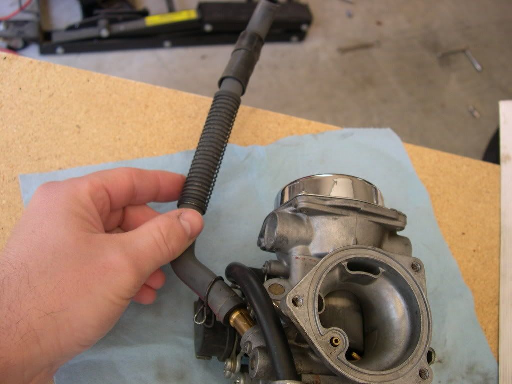
Honda VTX Forum banner

Throttle Position Sensor

7.6K views 49 replies 5 participants last post by  Tommy T  
2003 1300 has an electric fuel pump. Fails often.
Spark is difficult to see. Bolt on Cylinder Fins are mounted on rubber, not a good place to Ground to if looking for spark.

Common to have the two most forward wires on the ICM break right at weather seal.
5k ohms across the TPS, wiper to either end will be near zero to 5k, or 5k to zero.

Another ICM thread in the 1300 Step by Step.

Test some more and advise on results.. You can also use a pin and probe for
voltage on TPS. +5v and Ground, variable voltage between the ends.

A recent thread..https://www.vtxoa.com/threads/no-spark-carbed-vtx1300.475480/page-2#post-4711122 Last page was good for one owner.
 
Very strange. Rare problem.
One guy down under said he had a TPS trouble. Resistance was good.
Short your test leads, continuity test...

If you are convinced you have a TPS issue, you can buy one for $103 partszilla.
It says check on availability.
THROTTLE SENSOR SET 16060-MEA-671
Another alternative is Honda borrowed a few parts from the Civic.
I googled "honda civic TPS 16060"
Stare and compare...
 

Attachments

Probably have to pull the carb.
May be able to get access once you pull it off from the intake manifold.
I doubt that the ICM would do anything if no TPS was connected.
MR VTX Carb 101 Info and PIX.
 
Post on your thread...
A shop manual for 1300. TPS probably should be in the midrange, some space on either end.
 
Tommy--I want to ask you about your test meter.
Does it have several ranges for the Ohms measurement?
A 5k ohm resistor(TPS), to test requires an ohms range higher than the device under test.
 
Start over, begin with ICM connector wires. I really like to verify current. With Ign switch On, kill sw in Run check the wires from the Ign coils. Verify the Black +12v wire ICM power feed, test with a lamp. You should see +12 volts from the Ign coils. Tap a ground onto the Ign coils wire and check for a spark. Make sure the SP is grounded or get some bare wire and connect the SP metal shell together.. A verification on the Ignition pulse generator, it puts out 10 Volts AC peak to peak... Two back to back LEDs with one reversed and a 330 or 470 ohm resistor makes for a good indicator. Two wires to ICM, one has to see a Ground, either from Neutral switch or the Kickstand Up switch..

Driver Transistors are Open until a pulse is applied, then a Ground is applied to the Ign coil.
So +12v from fuse to Kill switch to Ign coils to Driver Transistor which pulses a Ground, current flows and a magnetic field is created. Ground removed and the magnetic field collapses produces up to high voltage in the primary(140 volts peak per my scope, 275 volts on peak voltage adapter). The secondary coil with many more turns in the coil creates thousands of volts at the High Voltage coil terminal.

 
So voltage at Ign coils Bl/w wire then go to the ICM and check voltage on Blue/yellow and Yellow/blue. If you have 12v there then tap it with some Ground. That Ground should create sparks at the sparkplugs.
 
Ign coils do NOT get +12v from the ICM.
The Kill switch provides +12v.
The ICM provides the Ground (pulses) to energize the coil.
The most forward two wires on the ICM are subject to breaking at the weather seal on the connector.
The insulation may shrink where the wire strands were.
Look at the ICM connector schematic and you can see the the wire locations.
You can pulse a ground from the ICM connector to the IGN coils but remove conn from the ICM.
Verify +12v to ICM on Black wire. Pull it some, if broken internally you may find your problem.
 
Tommy when you get back in shape I want you to try current measurements.
A bad connection, oxidation could be a possibility.
The ICM does not draw any noticeable current itself, but 3.9amps and 3.7 amps
on the Ignition coils may show where voltage drop could be.
 
We were interested in +5v at the TPS Y/R wire to the TPS Green/Orange Ground wire.
R/Y is the wiper aka variable terminal with 1 to 4 volts swing in reference to either end.

Kill switch puts +12v to Ign coils
ICM wires to Ignition coils are the Negative side of the coil.
ICM pulses a Ground to Ign coil , a magnetic field builds up.
ICM switches OFF the current to the IGN coil, magnetic field collapses,
a high voltage is created in the HV winding.

Remove the ICM connector, Turn IGN switch ON, Kill switch in RUN position.
Set your test meter to AMPS. Ground the Negative probe.
Now you activate the IGN coils using the Red test lead to Y/Bu wire(Rear coil) and the Bu/Y (Frt coil).
How many amps from each Ign coil??? If you remove the Spark Plugs(SP) put the SP back on the wires,
and GROUND the shell of each SP you should have spark when pulsed at the ICM wires.
 
Disconnect the Frt coil and see if TPS voltage comes up.
Swap the coils, see if trouble goes with the front ign coils.
Check wiring on and around the the frt coil wiring.
Any tachometer on this X???

Just reviewing....
Post #2 I asked about electric fuel pump(EFP). They die often.
EFP is connected to the front coil via the Fuel Cutoff Relay.
That could be the problem.
Convert to gravity flow. I did a field repair for someone last year.
Removed petcock to FP hose. Disconnect the FP hose to Carb.
Pulled the carb hose over to petcock.
Cut it to length with my dull knife.
The 2003 1300 VTX owner was able to catch up with his group.
 
Front coil wire should be disconnected at the coil to see if coil at fault.
Does it have a tach?? Someone had a double terminal which shorted causing the fuse to blow.
The wire could be shorted on the frame somewhere also.
Glad to see you back!

Did you remove the electric fuel pump wires and relay????
The fuel pump relay is connected with the Frt Ign coil.

Links to 1300 FP removal.. I added info on the 2nd page.