Honda VTX Forum banner

1300 Carburator: Scar Mod, A/F Mix&Idle Adj, Fuel Pump bypass

85K views 28 replies 15 participants last post by  Hans&Feet  
#1 · (Edited by Moderator)
OK, straight to the point -- for those running the "heavy breather" mods.

Keihin stock 195 main jet
Keihin stock needle, three shims (.06")
2 1/2 turns out on the A/F screw
Cut the slider spring to 5 1/16"

Details to follow for those that are not carb "savvy" -- NOTE: Fine tuning to come, but these settings will get you on the road and "running good" (and save money).

Now, down to the "basics"
I have wondered why so many people have been having problems dialing in their intake/exhaust systems via the carb circuit and took a little time to look at it a little closer today while experimenting with the stock Keihin needles (and yes, first reports are that they "ROCK") -- Those Japanese engineers knew what they were doing when they designed this 38mm carb, and there are some "tell tail" signs that they may have left for "performance" tuning when ordering the machining of parts that will be covered.

First of all... I have read several times about trimming the protruding tip under the "needle holder"... well, IT HAS TO BE DONE... just do it.. cut it in half with toenail clippers (the big ones, not the small fingernail clippers).. then put your toenail clippers in your tool box so they are there when you fix your buddies bike. Reason: If you run the dyno jet needle on the forth clip (or the stock Keihin needle with three shims or more as will be explained later) THE NEEDLE PUSHES AGAINST THE NEEDLE HOLDER AND DOES NOT ALLOW THE NEEDLE TO OPERATE FREELY. If you currently have the needle set like this, when you pull the slider piston from the carb body, try and "shake" the needle... IT IS STIFF ... no movement... this will mess you up -- the sides of the jet will be elongated AND the needle will not slide freely and you will wonder why you are not able to tune the bike properly... that needle has to be able to "shake around" freely when the slider piston is moving up and down -- If you EVER move the needle "up" to a position where the needle will not "shake" around once the needle holder is installed, cut more off of that "tip"... you will still have enough left to "screw" the spring onto it... but the needle movement has to be FREE.

Now, shimming the needle... That is a beautiful needle isn't it?? I have worked with a few different needles and the tapered variety is definitely the most intriguing not to mention delivering the most predictably metered fuel supply... if you compare it to the DJ needle you will notice that the Keihin is "swagged" (for want of a better term) and this may be to compensate for the nominal power drop commonly encountered with many systems in the mid range... this has been minimized with this needle design.. notice where the "swag" is most predominately exaggerated. Also notice that near the top of the "needle" there is a machining "groove" then under that there is yet another machining groove... well coincidently that first machining groove figures out to about .06" below the bottom of the needle head. Could it be an "indicator" from the engineer that even tho from the factory the carb meet EPA tuning requirements/emissions that carb performance would be maximized if shimmed to this point?? Who knows, but if you put a DJ needle running the 4th notch next to the Keihin needle, they match up at that point.. interesting... (don't forget to trim the tip under the needle holder to accommodate for this setting).

If you place three Radio Shack shims (or similar shims, equaling .06") under the needle head, then you should have a good starting point for a bike running fairly free breathing exhaust and intake... if you are running something slightly less than that, then use less shims... more shims equal more fuel... the APPROXIMATE fuel delivery of a Keihin 195 main jet is 195 cc/min and can be regulated with the height of the needle in the jet.

As always, the Keihin 55 Pilot Jet is most likely sufficient for maximum performance/tuning and the tuning procedure should be 2 1/2 turns out from the closed position during the entire tuning of the main jet process... if necessary the Pilot Jet can be "touched up" after the proper main jet tuning has been accomplished.

This is a "ballpark" tuning procedure and will get you on the road with a good performing bike.. fine tuning can be accomplished through following the steps as outlined by Factory Pro CV Carb Tuning Procedures -- Follow the steps religiously and you should have no problems.

RESPONSE: Most "tuners" run a shorter piston slider spring than comes in the factory stock equipment. If the factory spring is cut to 5 1/16" it should approximate the reaction time of the shorter spring that is supplied with the dyno jet kit... the factory spring appears to be marginally stiffer than the after market product, so this leaves a slight margin of error... if you are nervous about cutting slider springs, new ones can be had for a nominal fee from places such as ronayers.com: Online Shopping Motorsports Parts -- (Most people recommend placing the cut end of the spring down inside the slider tube and the uncut end "UP" into the underside of the cap/cover) Well, that just about concludes the elcheapo mod for making the bike run properly.

It would appear that the carb engineers at Keihin actually knew what they were doing. The factory jet may supply something close to what optimum performance is for the 38mm carb, if nothing else it will equate the performance of a straight cut 210mm main jet in fuel delivery if properly shimmed.

Larger jets of the Keihin shape can be bought through "Factory Pro" and after fine tuning, if it is evident that I require such jets, there will be a "write up" on that also. To date the bike pulls pretty good up to 83mph indicated in second gear. If there are some out there that require more than the Keihin 195 with the Keihin needle, they could order these jets... drilling is always an option, but this write up is not intended for the advanced tuner. -- Good luck and good riding.
 
#2 ·
Idle Circuit A-F Mixture and Idle Speed Adjustment

Idle circuit A-F mixture and idle speed adjustment, by Joe Licketto

To get the most accurate setting for idle speed mixture, you will need two (2) tools - a good vacuum gauge (similar to one part of a carb sync gauge set, or even a cheap old automotive vacuum gauge with a dampener to avoid too much fluctuation) and a (inductive) tachometer that attaches to a spark plug lead.

Warm your bike up to operating temperature, about a 5 minute ride should do.
- Attach your vacuum gauge to a "T"-fitting coming off the intake manifold between the carb and the cylinder head, maybe where your PAIR valve connects or connected to.
- Pick any spark plug wire and hook up your inductive tachometer.
- Start the bike and set the idle speed screw so the RPMs are 850-950.
- Begin by adjusting your A/F mixture screw in (leaner) until the RPM drops noticeably - you will note that the vacuum gauge drops its reading and becomes erratic, but the engine still runs.
- Bring your idle speed back up to proper range with the idle speed screw.
- Now adjust our A/F screw out (richer) in ÂĽ turn increments until you obtain the highest possible vacuum reading. Hopefully this will also be your highest RPM as well.
- Back the RPM down to proper range with the idle speed screw, again.
- Try ÂĽ turn in (leaner) and see if your vacuum and RPM drops. Continue turning it in using ÂĽ turns until the vacuum does drop off of its highest reading after setting the idle speed in the step just above.
- When the vacuum does drop, go back out (richer) the last ÂĽ turn.
Your idle mixture should now be correctly set. Remember, it's ONLY the idle circuit and possibly the first 1/8 throttle off-idle that you are affecting. This will also include when allowing the throttle to snap shut on deceleration. Any throttle position other than idle, should NOT be affected by this adjustment procedure.

You may need to apply a mild amount of choke (enrichener) in cool/colder weather so that the engine stays running at a high enough idle speed so as not to stall out for the first few minutes. After that, push the choke all the way in and ride on.
__________________
Author; Joe Licketto
 
#3 ·
pepsX's fuel pump removal

PepsX's Fuel Pump Removal


Don't bother replacing a faulty fuel pump (the '03 model VTX1300 had a fuel pump)
Simply use the pet**** and fuel line from the newer models. In a pinch (if you're stranded on the road) - you may simply run a fuel line directly from your existing pet**** to the carb....bypassing the pump completely.

pepsX wrote:
I just got my bike back on the road after removing a faulty fuel pump.
the sysmpton was: bike just died while riding, let it sit for 10-15 minutes, and it started and ran for 10 minutes, then died again. it acts just like it runs out of gas (it actually does).
after removing the fuel pump, i placed the pickup tube in a can of gas, applied 12v to it and it ran fine for a few minutes, then you can hear it pumpling slower and slower until it dies after about 2 minutes. disconnect the 12v and let it sit for a few minutes and re-apply 12v and it does the same thing.
here is what i did to replace it.
buy a newer model pet**** and fuel line. remove early 03 pet**** from tank and put in the new one, run the new short fuel line to the carb, tap into a vacume line (the new pet**** has a vacume shut off safety line).
i removed the old fuel pump by taking the seat off, taking out the battery, removing the battery box (a bitch), and removing the fuel pump. then put it all back together without the fuel pump.
use this thread for pic and part number to replace parts.
http://www.vtxoa.com/forums/viewtopic.php?t=170132&highlight=
thanks LozTX.
this is the third 03 I know that the fuel pump has died.
here is a pic of the battey box and fuel pump and hoses.
Image

it cost me about $135.00 for the pet**** and fuel line. a new pump cost over $400.00
hope this helps someone in the future.


Last update: 2006-11-26 18:52
Author: Ceetro
 
#4 ·
Removing A-F "D" screw by AZVTXtra

Removing A-F "D" screw by AZVTXtra


I purchased CyberHick's A/F screw, as I see the value in not having to make adjustments using a .22 shell bent to the "D" shape, nor was I willing to buy the tool from Honda for some $92. Because I was ready to embark on the change of the airbox, it seemed the right time to do it.

But I had on heck of a time with the .22 shell trying to get the screw out. To start, it is in a heck of a hidden place under the carb to the back, inside a collar. You can't see it without a mirror, so it's mostly by feel. No room for two hands, so it's a two finger balancing act. And there's hoses in the way, so nothing is simple. I kept thinking I "had it" and was turning and turning and turning. Then I'd discover (using the mirror) I had barely moved it. To get it out, you are turning it clock-wise (as viewed from the top of the bike).
This is the little jewel I was after:

Image


Well my .22 shell was getting beaten to heck and I got tired of re-bending the "D" shape to try to to make it "catch". So I started looking in the parts drawers, and stumbled upon an electrical crimp "bullet" connector. The blue plastic part was almost exactly the size I needed.


Image


By "force fit" while still in the carberator, it "grabbed", and spinning it out was easy from there.


Image


Hopefully my experience will save some of you a couple of frustrating hours.

So I didn't use a .22 cartridge, I used an electrical "bullet connector" ... seems like will still stayed in the firearms arena.


Last update: 2007-04-01 18:50
Author: Ceetro
 
#5 ·
If I may, I'd like to add some additional info to the SCAR mod för those of you living in metric countries.

The width of the needle at the top, just under the hat is just below 3mm. The hat itself is about 6mm.
An M3 shim worked perfectly for me and I estimate it's thickness to the same as SCAR posted above.

Hope this helpes someone :thumbup:
 
#6 ·
Factory Pro Jet Kit

Factory Pro jet kit install

This write up is for installing a Factory Pro jet kit in VTX 1300. Portions of this write up are from Scar mod write up Buy TennX. Those Portions will be quoted to Tennx and Scar.

the factory pro jet kit contains


  1. Factory pro needle
  2. 5 E-clips
  3. Main Jets 225, 220, 215, 210
  4. 58 slow jet
  5. replacement socket cap screws for the float bowl
  6. d shape tool for adjusting A/F or pilot screw
  7. documentation


First remove the seats, gas tank and breather housing

Quote taken from Scar mod post By TennX
NOW the carburetor is EXPOSED.

Sitting on top of the carb you will see the vacuum chamber cover.
Image


Remove the cover and then remove the compression spring under the cover.

Image


Now gently grab the diaphram/piston rubber and pull it out.. the Vacuum piston (slider piston is what most old timers call it) is attached to the diaphram and the whole package will come out with it.

Image


Look at the slider piston and you will see a tappered "needle" sticking out the bottom of it, that is the jet needle.
Image

Look inside the slider piston and you will see the Jet needle holder.

Image


The jet needle holder is next to be removed.. you will see in the center of the holder it will accept a Phillips head screwdriver which can be used to "unscrew" the cam locks, BUT the "best" method is to use a small socket and fit over the head of the "cap" and unscrew the cap... I'm thinking it's an 8mm.. difficult to recall those things sometimes at my age, but you'll discover the correct size. Twist the cap counter clockwise just as tho you were unscrewing any "standard" nut or bolt and you will feel a "pop" after making a very small motion.. that was the cams unlocking.. the cap can now be removed, it is "unlocked".

Image

Under the needle holder cap there is a small spring "screwed" onto a plastic "tit" protruding from the bottom of the cap... well actually the "tit" has no threads, so the spring is not "screwed" on, but consider it so... instead of "pulling" the spring off and distorting it's shape, give a "light force" pull on the spring while unscrewing it from the "tit" and set the spring aside. Take some TOENAIL clippers (those are the large ones, not to be confused with fingernail clippers) and "snip" the "tit" in half.. that should be enough for the factory pro needle and still provides enough remaining "tit" for the small spring to be screwed back onto... set the needle holder cap aside.
Image

Remove the needle from the slide. Take the Factory Pro needle out of the kit and install the clip in the 4th slot down from the top of the needle. Factory Pro recommends the fourth slot for a start point. The top of the needle is the end of the needle that has the slots for the clip. Position one is the slot at the end of the needle. Position 5 is in the middle before the taper starts. Ensure the e-clip is in the slot properly. The back side of the clip has a tab on it. This tab must be in the slot on the needle. If it is not the needle will not sit in slide properly it will lean to one side. Put the needle into the slide. This a picture of the Factory Pro needle with the E-lip on the fifth position.


Take the SMALL spring that was unscrewed from the underside of the needle holder cap and screw it back onto the shortened "tit" under the needle holder. Put the needle holder cap into the slider piston with the small needle spring tensioner sitting on top of the needle head. (If the 8mm socket is placed onto the top of the needle holder cap "nut" the tension is enough to hold the cap.. the needle cap holder can be easily inserted into the slider piston with this method utilizing a socket extender). Twist the needle holder cap clockwise as tho "tightening" and you will feel the cams lock into place... that's it, the needle holder is locked. If enough of the "tit" was trimed, this should be a relatively easy "twist"... Hold the slider piston with one hand and "wiggle" the needle with the fingers on the other hand... the needle should "wiggle" (movement), this assures true alignment into the emulsion tube
. If the needle is "stiff" and won't "wiggle", then the "tit" was not trimmed enough ... go back and trim more from the tit until free needle movement is achieved.

Replace the slide diaphragm assembly. When replacing the diaphragm and slide carefully push the diaphragm towards the needle so that the diaphragm is pointing down towards the needle.
Image

This will make it easier to install the diaphragm gasket into the groove in the carb.
Image

Install the spring into the slide. If cut the slide spring (not needed with Factory Pro Kit but some will cut it for different tuning) Make sur the cut end is down inside the slide. Install the vacuum chamber cover.. NOTE: There is an irregular "shape" in the cap that must be matched to it's mating surface when remounting, this is what the manual calls the "tab and air passages"... "Snug" the vacuum cap screws and continue reassembly.


Loosen the clamp on the carb side of the intake manifold. An extra long screwdriver works well on the clamp. losen the choke knob from the bracket and lift the choke knob from the bracket. Pull the carb out of the manifold boot and let it hang. Remove the accelerator pump linkage be careful not to loose any of the small parts of the linkage. After the linkage is removed put the screw and washers and spacers back into the hole and screw them in a little so you don’t loose the parts. Loosen the screw facing sideways on the bottom of the bowl. Put a rag under it this will drain the gas out of the bowl. Tilt the carb out and remove the float bowl screws. Push on the screw driver with strong force. The screws strip very easily. If the screw head strips use small pair of locking pliers to remove the screw. Remove the float bowl carefully so you don’t damage the floats. Clean the bowl if there is any residue in it. Use a flat tip screwdriver and remove the main jet from the Jet holder. Put in the recommended main jet for your intake setup. The recommended jet size is on the sheet that came in the kit. This jet is a start point it may not be the correct one for your bike but that’s part of rejetting (trial and discovery). Use a Flat head screw driver and remove the slow jet. Install the #58 slow jet from the factory pro kit. Again this may not be the correct jet but it’s a start point. Reassemble carb and accelerator pump linkage.

Under the carb is the A/F screw (see manual).
If The long boy screw or Glens A/F screw is used remove the A/F screw and replace it. If the stock screw is used use the D-head tool in the jet kit screw in the needle until it LIGHTLY seats or stops turning ... don't get anal about this and over tighten or damage could be caused to the needle/jet mating surfaces . If you error on "seating", error on the LOOSE side, final tuning will not be affected by a minute discrepancy of "seating" at this stage of tuning. Turn the A/F screw OUT 2 turns.


Push the carb back into the manifold boot. Note the tab on the back of the carb were it goes into the manifold boot. There is a slot in the manifold boot that this tab goes into. After carb seats into manifold tighten manifold clamp. while tightening the clamp reach under the carb and feel the clamp and make sure the bottom of the clamp is in the proper location on the bot. sometime the clamp will tilt to one side.
Reassemble the airbox and fuel tank and seats. remount the choke in its mount

Before firing the engine, look at the CHOKE KNOB and push it in all the way... any flexing of the carb while working on it will flex the choke cable and pull the choke out... it will not run properly with the choke pulled out AT ALL and final tuning cannot be achieved.


On initial start do not use the choke you’ll have trouble starting it


Attachments

#8 ·
Jet conversion chart

I thought this might help some people. There's a lot of question about what equals what when it comes to jets. Stock Keihen and Factory Pro jets are measured numerically in 2.5 increments, while DJ jets are measured by diameter, and Mikuni is measured by flow rate (we don't use these). FYI, If you have Cobra or Thunder kits they are using DJ jets. The DJ jets flow at a different curve due to beveled edges. In reality there is no direct comparison between any of these jets due to design differences.
We are often asked for a "cross reference" sheet that compares our main jets to Mikuni or Keihin. The fact is you cannot directly interchange the jets for a given size. Many things affect fuel flow through a jet of the same orifice size. The entry and exit tapers of our main jets differ from those of other companies. Due to this, the fuel flow changes as a function of velocity through the carburetor venture. This means that two jets of equal orifice size will have a different fuel flow curve relative to intake air speed. At a certain speed the two may flow equally, but a change in velocity changes the flow characteristics. The Dynojet main jet hole size is measured in millimeters. For example, a DJ142 has a 1.42mm hole.


Michael Cory
Research & Development
Phone: 800-992-4993 EXT. xxx
Michael@Dynojet.com
Due to these differences it is not advised to run DJ needles with stock or FP jets and vise-versa. They are not designed to work with each other.

Although there is no direct conversion, these are the diameter measurements for each manufacturer. They will at least get you in the ballpark, but fine tuning will get you the rest of the way there!

So here is a chart to help everyone out(Stock jet for 03-07 is labeled in RED, 08-09 is labeled in GREEN.):

Width------Kehein (FP)# -- DynoJets # -- Mikuni #

0,0350---- 92,5--------- 92----------- 86,3
0,0360---- 95----------- 94----------- 88,1
0,0370---- 97,5--------- 96----------- 90,0
0,0380---- 100---------- 98----------- 91,9
0,0390---- 102,5------- 100---------- 93,8
0,0400---- 105--------- 102---------- 95,6
0,0410---- 107,5------- 104---------- 97,5
0,0420---- 110--------- 106---------- 99,4
0,0430---- 112,5------- 108--------- 101,3
0,0440---- 115--------- 110--------- 103,1
0,0450---- 117,5------- 112--------- 105,0
0,0460---- 120--------- 114--------- 106,9
0,0470---- 122,5------- 116--------- 108,8
0,0480---- 125--------- 118--------- 110,6
0,0490---- 127,5------- 120--------- 112,5
0,0500---- 130--------- 122--------- 114,4
0,0510---- 132,5------- 124--------- 116,3
0,0520---- 135--------- 126--------- 118,1
0,0530---- 137,5------- 128--------- 120,0
0,0540---- 140--------- 130--------- 121,9
0,0550---- 142,5------- 132--------- 123,8
0,0560---- 145--------- 134--------- 125,6
0,0570---- 147,5------- 136--------- 127,5
0,0580---- 150--------- 138--------- 129,4
0,0590---- 152,5------- 140--------- 131,3
0,0600---- 155--------- 142--------- 133,1
0,0610---- 157,5------- 144--------- 135,0
0,0620---- 160--------- 146--------- 136,9
0,0630---- 162,5------- 148--------- 138,8
0,0640---- 165--------- 150--------- 140,6
0,0650---- 167,5------- 152--------- 142,5
0,0660---- 170--------- 154--------- 144,4
0,0670---- 172,5------- 156--------- 146,3
0,0680---- 175--------- 158--------- 148,1
0,0690---- 177,5------- 160--------- 150,0
0,0700---- 180--------- 162--------- 151,9
0,0710---- 182,5------- 164--------- 153,8
0,0720---- 185--------- 166--------- 155,6
0,0730---- 187,5------- 168--------- 157,5
0,0740---- 190--------- 170--------- 159,4
0,0750---- 192,5------- 172--------- 161,3
0,0760---- 195--------- 174--------- 163,1
0,0770---- 197,5------- 176--------- 165,0
0,0780---- 200--------- 178--------- 166,9
0,0790---- 202,5------- 180--------- 168,8
0,0800---- 205--------- 182--------- 170,6
0,0810---- 207,5------- 184--------- 172,5
0,0820---- 210--------- 186--------- 174,4
0,0830---- 212,5------- 188--------- 176,3
0,0840---- 215--------- 190--------- 178,1
0,0850---- 217,5------- 192--------- 180,0
0,0860---- 220--------- 194--------- 181,9
0,0870---- 222,5------- 196--------- 183,7
0,0880---- 225--------- 198--------- 185,6
0,0890---- 227,5------- 200--------- 187,5
 
#9 ·
Refer to this before you even think about opening your carburetor!!

There are so many questions on here about tuning, and not too many riders seem to understand exactly what they are adjusting. The following information is the BEST explanation of CV Carburetor operation I have found. The Keihen CVK40 is a Vulcan carburetor, but is basically identical in design to the VTX's 38mm. Please, review the following info for a more thorough understanding of your bike's fuel system. I have edited a portion which talked about special pilot adjustment tools, but Glen's VTX Garage can supply the proper tools. I really think this can help a lot of members!

**The following is from http://www.gadgetjq.com/keihin_carb.htm**


Keihin CVK40
The Care & Feeding Of Your Vulcan Carb

Originally posted by Redondo Ron on a now defunct AOL website in 1998. The pictures and text are all his. Many thanks.


Part I - How It Works


THE BASICS - Mixing and Delivering
Image

While most of the following information applies to all CV carbs, and to some extent all carb types, this article is specific to the Keihin CVK40 found on many Kawasaki motorcycles (KLR's and Vulcans) along with some Harleys. If you need replacement parts you'd be well advised to get them from your local Harley Davidson outlet. They will be less expensive than ordering through your Kawasaki dealer and, in most cases they will be 'in stock'.


The CVK40 is technically a bleed type carb, with a variable venturi that's controlled by constant velocity (CV). It's also known as Constant Depression or Constant Vacuum. The 40 in the name represents a 40 mm venturi exit diameter. Wonder why 'K'awasaki added the K...?


BLEED TYPE CARBS - Let it Bleed

Image
Most carbs have a one piece needle jet. On the CVK40 it consists of a collar and what Kawasaki calls a holder. Most 4-strokes have pin holes along the length of this brass jet. These pin holes allow air from the air jet to premix with fuel from the fuel jet to start the mixture emulsification process before it enters the venturi. Primary type carbs use a solid jet, (no pin holes).


VARIABLE VENTURI - Getting Sucked In


Image

A venturi is a tube with a convex taper, (one end wider than the other). As air enters the wider end it's squeezed into the narrower section of the tube, lowering the air's pressure. The area of lowest pressure is just past the narrowest point and is called the depression. This has always seemed counterintuitive to me, but Bernoulli's Principle outlines the fluid dynamics involved in this effect. This lowered pressure, or comparative vacuum is separate from the engine vacuum. A variable venturi varies the venturi diameter at the depression
by raising or lowering an obstruction. This obstruction is called a slide. On a CV the slide
is called a piston or diaphragm valve.


CV or SLIDE CARB - The Great Compromise

Both the CV and conventional slide carbs are classified as variable venturi carbs. The slide on a conventional carb is directly connected to the throttle cable. Twist the throttle grip and the slide is raised in the venturi. On a CV carb the throttle cable is connected to a butterfly valve that varies the volume through the venturi. It's not the throttle, it's the pressure difference from the venturi to the outside atmosphere that moves the slide.

So which type is better? That depends on what you want to do. The manufacturers will tell you the CV is the next best thing to electronic fuel injection. It does feed a precise amount of mixture to smooth out throttle response, reduce pollution, and stretch your fuel budget and gas tank range.

This is great for tarmac cruising and feeling warm and fuzzy about doing your part to reduce global warming while pocketing some spare change. It sure makes it easier for the manufacturers to get the EPA approval stamp on the bike.

But what if you feel that no matter how much you hop up your little beast, you're never going to match the belching of that cager in the gas guzzling V-12 ? What if you don't mind spending more for gas, and when you go off-road you want a burst of power to blip over obstacles or steer through a wash without fanning your clutch while waiting for the vacuum to build in the venturi? If you can discipline yourself to control the throttle so that you don't bog your engine, then you want a conventional slide carb.


40 MM -Size Matters

Image


With the same engine and carb design,
a 38mm diameter venturi will more
accurately meter the mixture on the low
end, while a 41mm diameter will do a
better job of supplying mixture at higher
engine speeds. It's another factor to
consider if you replace your carb.


MIXING AIR AND FUEL - All In the Pressure

It all starts in your engine. Think of your thumper as a big pump,
happily sucking and blowing down the road. During the intake stroke
the engine's piston descends in the cylinder. This creates a void that
sucks in whatever is on the other side of the open engine intake valves.
Unless the engine intake valves are open, the carb is not being sucked
on by the engine. This vacuum action powers the carb.
Look at the 4-cycles of our 4-stroke
Image
thumperpumper.


1) Intake - piston pulls down sucking mixture in.
Intake valves open, exhaust closed.
2) Compression - piston goes up.
Intake and exhaust valves closed.
3) Ignition/Power - piston forced down.
Intake and exhaust valves closed.
4) Exhaust - piston goes up blowing out burned gas.
Exhaust valves open, intake closed.

Each time the piston goes up and down, (two of the four strokes), one revolution has occurred. It takes two revolutions to complete the four strokes, or one-half of a revolution to complete one of the four strokes. At redline, your engine is sucking on the carb at a rate of over 60 times per second. At idle it's around 11 times a second. The math below shows that with a 651cc displacement, a theoretical maximum of between 7 and 40 liters of mixture are sucked in each second.

7500 .......(engine RPM)
/ 2 ...........(2 revs per intake stroke)
= 3750 .....(intake strokes per minute)
/ 60 .........(seconds per minute)
= 62 ........(intake strokes per second)
x .651 ......(engine displacement in liters)
= 40.69 ....(liters per second)

These numbers assume 100% efficiency. Mister_T calculates about
38% efficiency at idle. So these numbers are only to illustrate
the relative difference in volume from idle to redline.

Remember Bernoulli's effect in the venturi? Sitting below the venturi is
the fuel float chamber which is vented to the outside of the carb to match
atmospheric air pressure. The fuel in the float bowl is also 'vented' to the
low pressure of the venturi through the starter, pilot and main fuel jets.

So you can think of the float chamber as being pressurized in comparison
to the partial vacuum of the venturi. The fuel naturally tries to fill in the
low pressure of the venturi's depression by injecting itself through one,
or a combination of the three fuel jets.


THE ODDS - Skinny or Fat

Image

Any carb problem boils down to either it's too rich, (too much fuel or too little air), or it's too lean, (too much air or too little fuel). The 'mixture', (a mixture of fuel and air, your engine's 'food'), is theoretically ideal at around 15 parts of air to one part of gasoline
by weight, (not volume). The outer limits are 12:1
and 18:1 .

Too rich and you're wasting fuel, spewing more pollutants, diluting your oil, fouling engine parts, and performance suffers. Too lean and you run the risk of detonation, engine operating at higher temperatures, and performance suffers.

An air-cooled engine needs to run richer (more fuel)
to aid in engine cooling. This is another plus of our water-cooled system to balance out it's disadvantages.


PARTS - Is Parts
Image

Supplementing the factory manuals, the following text and photos should make it easier to understand how the carb works. The parts are broken into the following groups:


Image
FLOAT SYSTEM - You're Floating In It

Image
The float system acts as a fuel reservoir to meet engine

demand. The float is hinged on a pin in the float boss. It
rises and falls with the fuel level in the float bowl. The small
metal tang integrated in the plastic float supports the float
valve, aka float needle. As the fuel in the float bowl rises,
the float valve is pushed into the valve seat, until it's high
enough to shut off the fuel flow to the bowl. The level in
the bowl drops lowering the float which pulls the float
valve from it's seat, and fills again.


Image
STARTER ENRICHER - KLR Morning Coffee


Image
This system is referred to as the

choke. But that's a misnomer. When
you apply the choke lever, what
you're doing is retracting a plunger
that opens a tube connected to the
starter jet, allowing additional fuel
to enter the venturi just below the
vacuum hose nipple. It supplements
the pilot system at start up.


PILOT SYSTEM - Steering You to Better Lows


Image
The primary purpose of the pilot system is to supply the mixture at idle. It continues to supply fuel throughout the entire throttle range, but after about 1/8 throttle is reached the MAIN SYSTEM starts to put out an increasing percentage of the total mixture up to full throttle.

When you set the idle with that big screw on the right side of the carb, what you're doing is covering or uncovering one or more of the four small holes that are drilled into the venturi, (leading to the pilot jet) just under the butterfly valve, and letting more or less air pass the butterfly. When you adjust the pilot screw that's under the carb, you are varying the amount of air premixing with the gas before it enters the venturi.


MAIN SYSTEM - The Meat

Image
Image

As you advance the throttle cable that's connected to the butterfly valve, the butterfly opens to allow more air through the venturi. This increases the vacuum effect that
is transferred up
through the vacuum
drilling (the hole you
bored out for the
Dynojet kit), on the diaphragm valve (slide), that leads
to the TOP diaphragm chamber.


Image

The top chamber is separated from the BOTTOM chamber
by the rubber diaphragm. The bottom chamber is open to
atmospheric pressure from the airbox by the crescent shaped
casting on the top of the venturi. When the vacuum in the top

chamber rises sufficiently, the constant ambient pressure
of the lower chamber, helps the diaphragm valve overcome
the downward force of the diaphragm spring, and it rises
from the venturi.

As the diaphragm valve is raised from the venturi
depression (lowest pressure area), the needle is pulled
further out of the needle jet, exposing a thinner portion
of the needle taper which allows even more fuel to rise
into the venturi to meet the increased engine demand.


COASTING ENRICHER - Feeding a Closed Mouth

Image
You're blasting down the trail and you see a

hairpin coming up, so you close the throttle.
This closes the butterfly valve. You and your
400lb baby (the bike, not the other love of
your life), are still rolling with inertia, keeping
the engine revs high. Now it can't get the
mixture it's trying to suck in because the
butterfly valve is closed, blocking the air flow.


To compensate for this there's an air jet in the lower
Image

diaphragm chamber that transfers ambient pressure to
one side of the coasting enricher's spring loaded cut off
valve. The excess vacuum in front of the butterfly valve
is transferred to a drilling that leads to the other side of
the cut off valve. This sucks it open, allowing the pilot
jet to feed more fuel to the engine preventing an overly
lean condition. (Pop. Pop. Pop.)


Originally Posted by

Redondo Ron
12/98
 
#10 ·
The "turns out" on the A/F are directly related to the Needle's Shim and the Pilot Jet.. The needle's clip position to a lesser extent, but still would need fine tuning if you move it.


Factory Carb with SCAR Mod should be 2 1/4 to 2 1/2 turns out from lightly seated.

Factory Pro Stage 3 58 Pilot (factory is 55) you can take about 1 turn off of that.

Im 4th clip position, 58 pilot and it seems to like 1 to 1 1/4 turns out from lightly seated.

-Gonz
 
#11 ·
Thanks!!!

I just wanted to thank you for posting the Scar Mod info. I have a 2006 Honda VTX 1300s with 26000 miles on it. Shortly after buying the bike (brand new) I put some Cobra slip-on exhaust on. Everyone told me I would have to do a jet kit inorder for the bike to run correctly. Well almost 25000 miles later it started loosing power so I tryed A Dynojet kit and after 3 days of frustration because no mater what Dynojet or Cobra told me what I needed to do nothing worked. Then I found your post and went back to the stock needle and jet. Then did the Scar Mod exactly as you described and low and behold on the first shot my bike hasen't ran this good since I first got her!

Thanks,
Rkovic
 
#12 ·
Fuel Pump bypass 2003 1300

My fuel pump packed in after 55,000 miles on my 2003 1300S , it gave a few indications that it was on it's last legs , with the bike dying and after a couple of minutes the pump was fine again

So I ran new fuel line from the tank to the carburetor

It's real easy to do with a few tools

Hex size 5 , 6

Sockets 10 mm ,12 mm

Phillips screw driver

Needle-nose pliers

Electrical tape

Rags/paper towel

1) Remove seat and right rear side cover

2) Remove tank and right rear side cover for better access
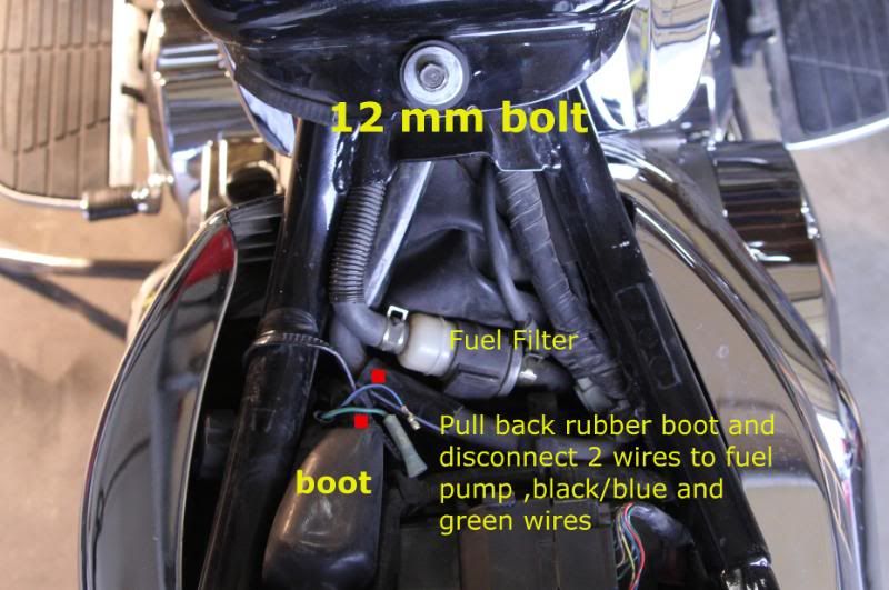
(Turn gas OFF , unplug 2 green speedo connectors under right front of tank , lift clips , don't wreck em, mark with a sharpie for ease of installing))((,pull off tank vent hose under right rear of tank, pull off fuel line at petcock)

3) Pull back rubber boot and disconnect 2 fuel pump wires ( blue/black, green)

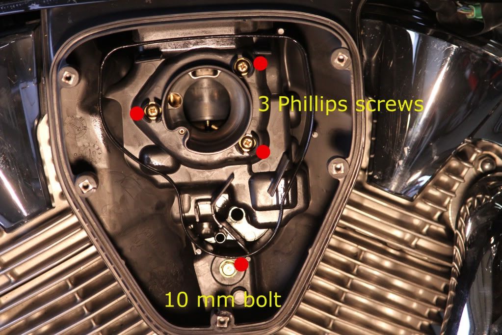
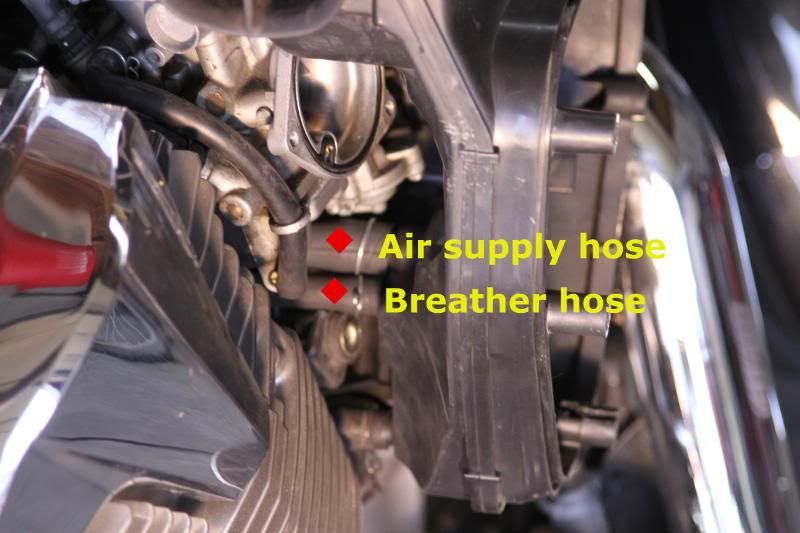
4) Loosen air box by removing the 5 screws holding on the cover ( DO NOT
over tighten when installing) , remove 10mm bolt and 3 Phillips screws ,
Undue the tab at the top of the air box and gently pull back being careful
to not pull the air box from the attached air and breathers hoses

5) Disconnect fuel line from carburetor

6) Install new 3/8" fuel line with inline fuel filter between jugs , approximately 12" in length

I used the rags to catch the few drops of gas when the lines were removed and the tape to cover the wires and cap ends of old fuel line

TURN OFF GAS WHEN MOTORCYCLE IS PARKED

Image


Image


Image


Image


Image


Image


Image


Image
 
#16 ·
And lightly seated.. like kissing a new born baby... just barely touch... and turn out..
Thanks, i have a D-Shaped socket already so i think ill be doing this as soon as my pipes arrive. I dont really want to put an intake on the bike as i like the look of it the way it is, im just going to put in a KN filter with the cobra speedsters. Fine tuning is going be a b*tch
 
#17 ·
Guys, did the Scar mod today! Very easy and great write up. Thanks. Darn breather hoses were a son of a to get back on. Also i found a very nice/easy way to get to the A/F screw. I bought this bit http://www.amazon.com/gp/product/B003CMWC4U/ref=oh_aui_detailpage_o07_s00?ie=UTF8&psc=1 via amazon and used a wobble extension 8" i think on a 1/4 driver. Was able to dial it in easily. Just need a flashlight set up to see. I made marks on the socket for the D tool bit. I can take some pics of my set up if needed. Good luck
 
#20 · (Edited)
Removing 2003 1300 VTX Fuel Pump---more info.
I had a chance to remove a dying, run dying, dead FP from a VTX.
I see we have a few pix here for reference.
Knight-- https://i212.photobucket.com/albums/cc307/Picbybrad/Fuel pump bypass/IMG_66091b.jpg
PepsX-- https://i18.photobucket.com/albums/b110/pepsX/batteryboxandfuelpump.jpg

Removed seat, lifted fuel tank:
I pulled the fuel hose off the petcock, push/pulled it out to the FP, cut the hose off.
I forgot to remove the fuel hose wire clip and it slipped onto the cyl head.
The hose from FP(or fuel filter) to Carb was cut off at the FP(or fuel filter) and pushed onto the petcock.
I used a flat hose clamp to hold fuel hose onto petcock.
Last thing to do is to Disconnect the Fuel Pump Relay connector to remove power to the FP.
Removing FP and filter is your choice.
Fuel petcock is a standard NON-vacuum petcock. Fuel should be turned off when parked.
OR get a vacuum operated petcock.
Reference to a 2004 thread of 2003 1300 FP failure.
 

Attachments

#21 ·
LINK to MR VTX CARB 101
 
#22 ·
Whenever I need to check my petcock, I create vacuum to it with a injection(see picture)
I have even driven the bike a few days with vacuum created with the injection, and I now have one injection tube (without needle) with me in my toolbox all the time. Just in case I have my doubts about the functioning of the petcock or to check if there is a vacuum problem.
Of course I block of the vacuum line to the carb, if I need to start the bike while applying vacuum to my petcock via an injection tube.
Image