
I wanted to document my carb tear-down, in case anyone wanting to do this with/without the manual could do so pretty easily. I will also have this in Word format to e-mail out to anyone needing it. I did a search for this and didnt find anything like it on the board. It might be somewhere else, though, so if I duplicated the effort, I apologize in advance. The steps are quoted directly from the manual, and anything I add will be highlighted in red. The first steps involve other procedures I did not document...this is strictly getting just the carb off and tearing it down.
Step 1: Drain the coolant.
** This involves taking the tank off, which I already had off anyway.
** You do not necessarily need to drain the coolant, but you will have to burp the air out of the system when everything is reconnected.
Step 2: Remove the right front cylinder head shroud (top fins).
Step 3: Remove the air cleaner housing (or aftermarket air kit).
Step 4: Disconnect the fuel hose from the carburetor.
![Image]()
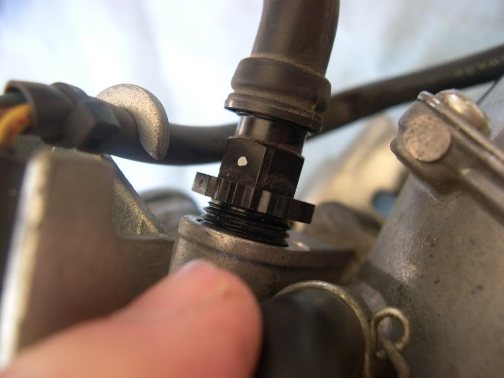
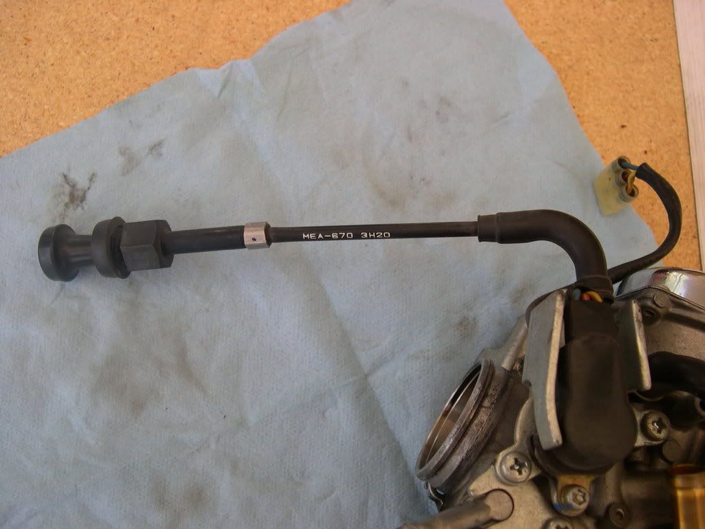
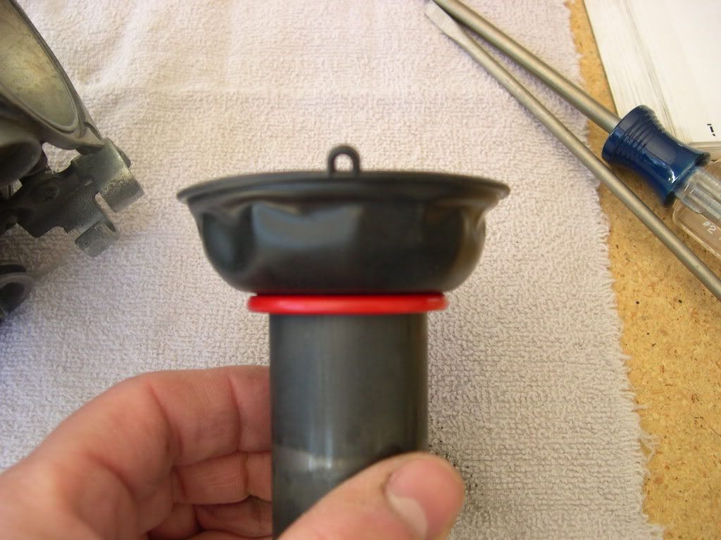
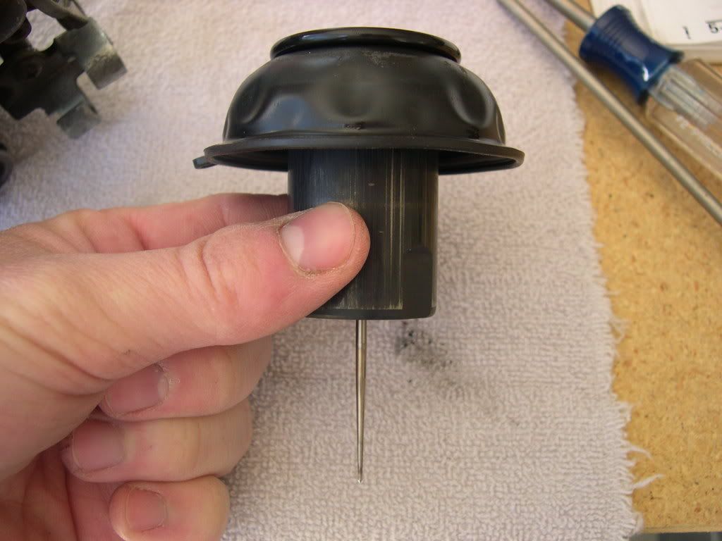
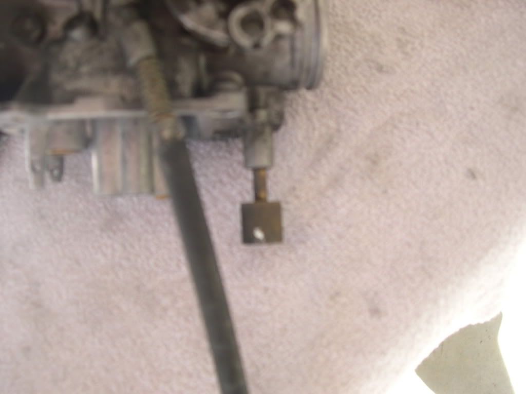
Step 5: Slide the rubber cap off the starting enrichment (SE) valve nut.
Step 6: Loosen the SE valve nut and remove the SE valve from the carburetor.
** It helped to take the choke knob off it's holder on the pet****-side, which I did.
![Image]()
Step 7: Disconnect the throttle position sensor connector.
** It's the white connector that is next to the neck of the frame...you can't miss it. It's already unplugged in the following picture.
![Image]()
Step 8: Remove the throttle cables from the cable stay and disconnect them from the throttle drum.
** I'll get a picture of this when I put the carb back together...forgot to snap one during the tear-down.
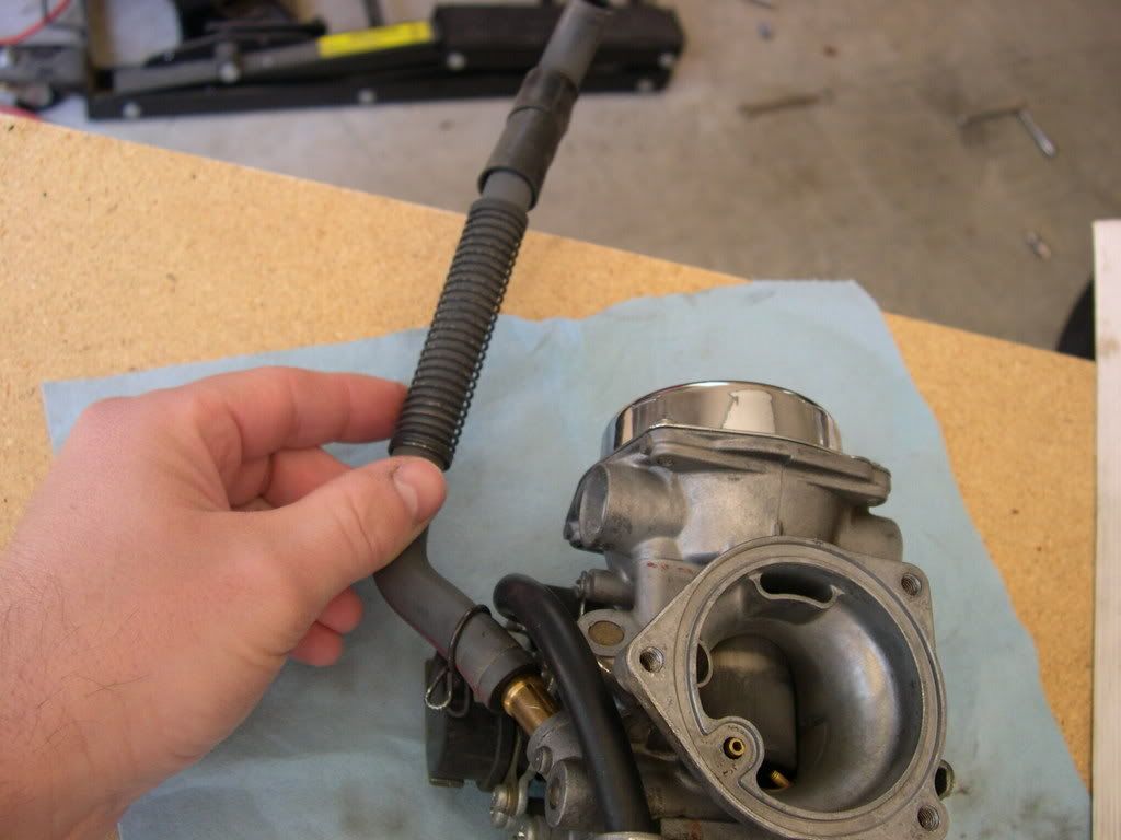
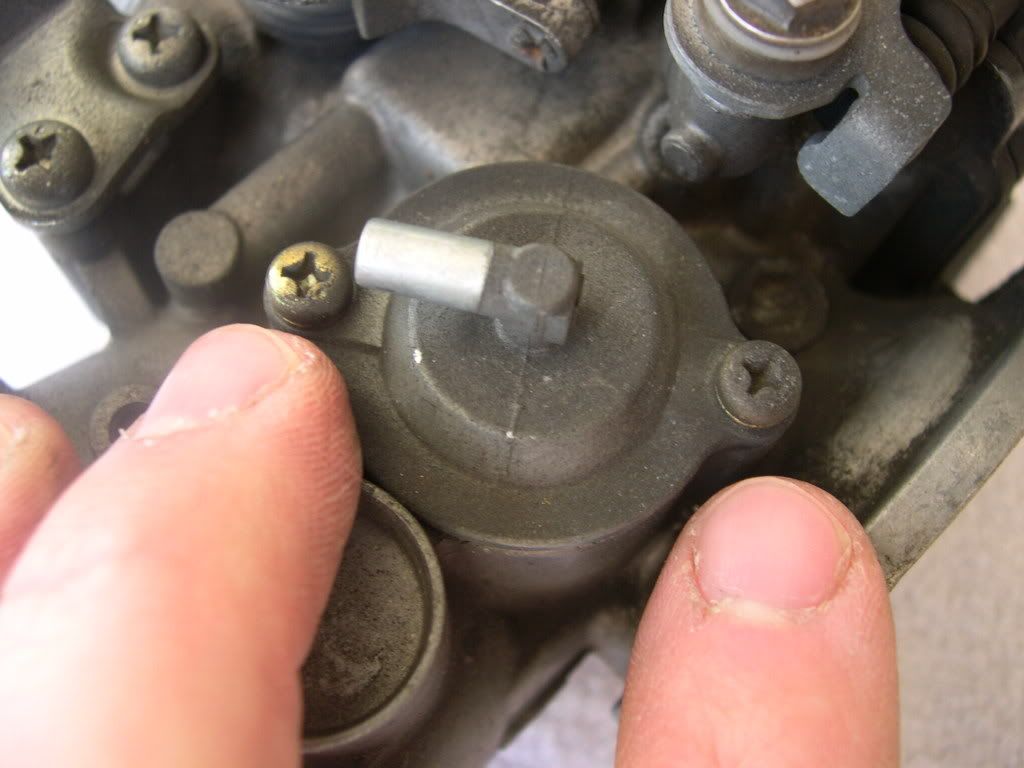
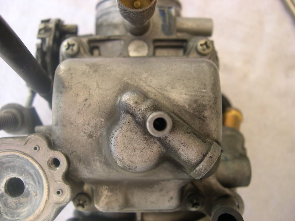
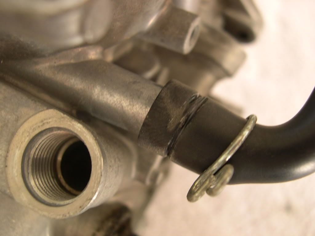
Step 9: Disconnect the vacuum hose from the carburetor.
![Image]()
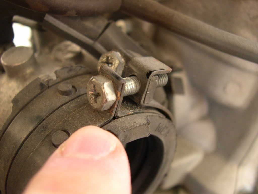
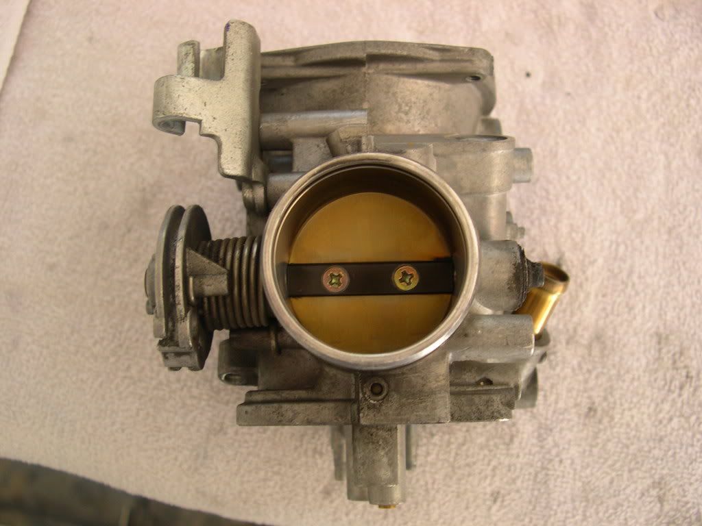
Step 10: Loosen the carburetor insulator band screw and remove the carburetor from the insulator.
![Image]()
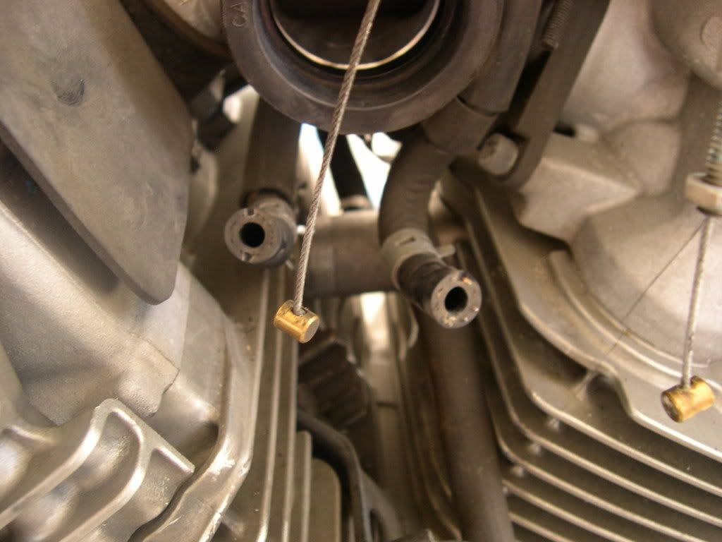
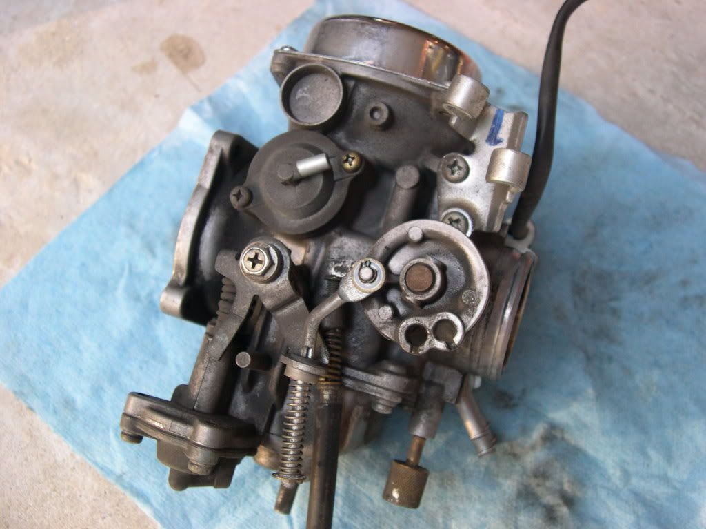
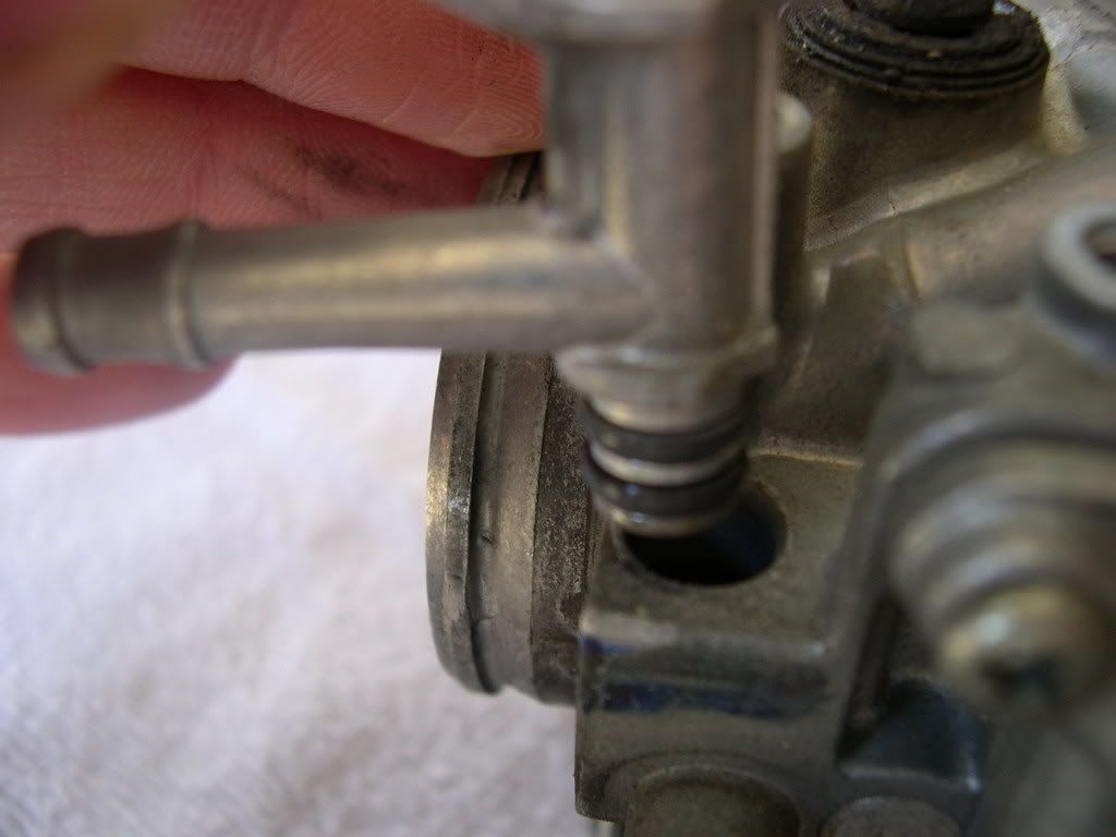
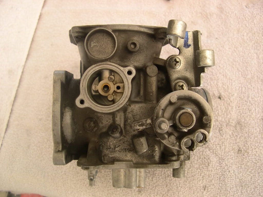
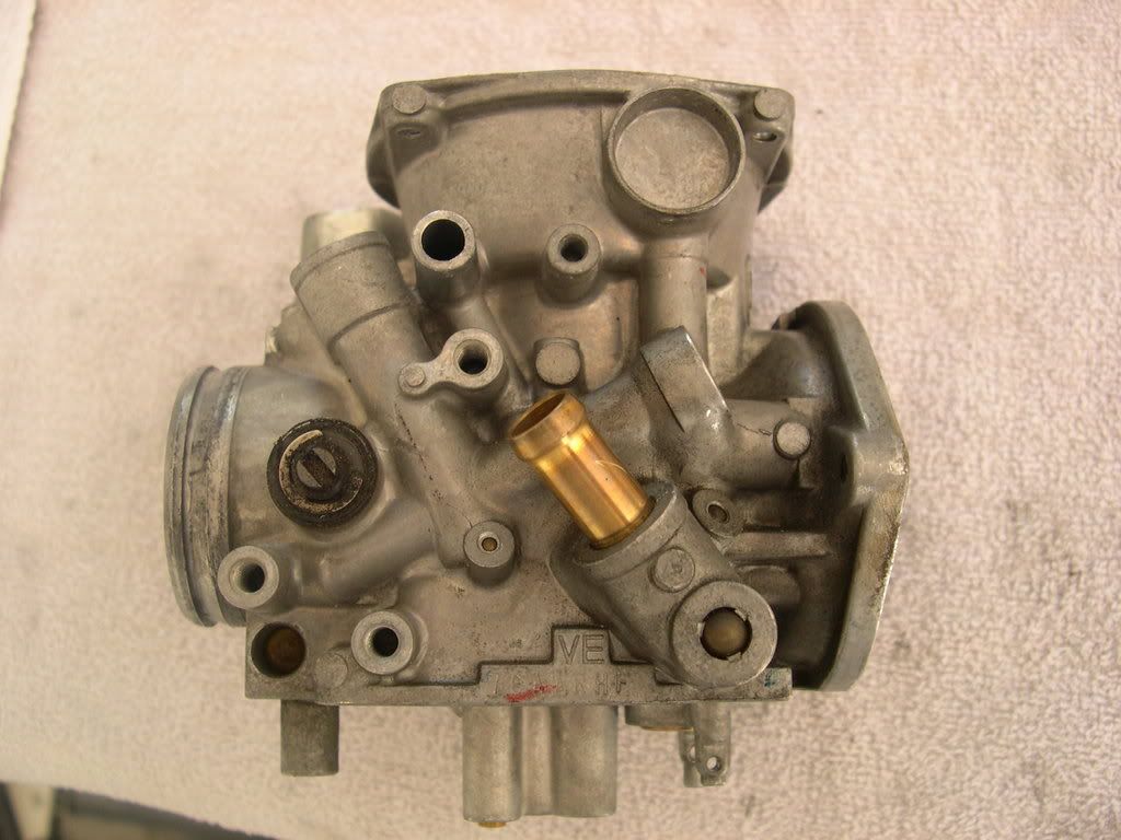
Step 11: Disconnect the water hoses from the carburetor and remove the carburetor.
![Image]()
![Image]()
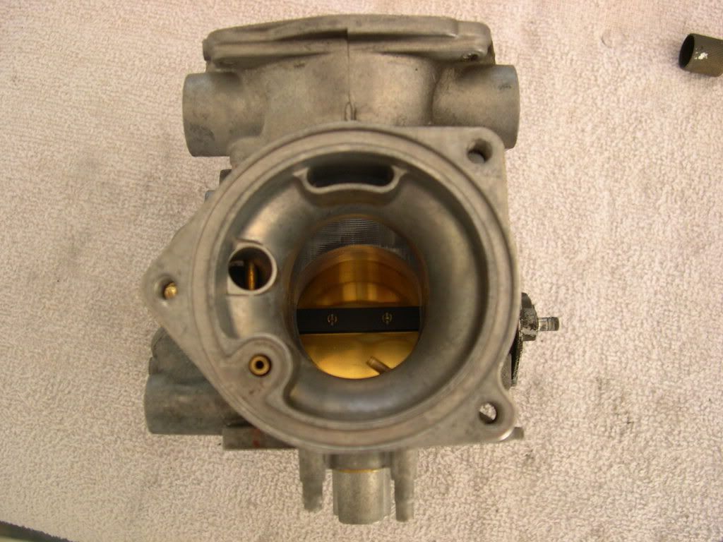
Step 12: Seal the intake manifold port with tape or a clean cloth to keep dirt and debris from entering the engine.
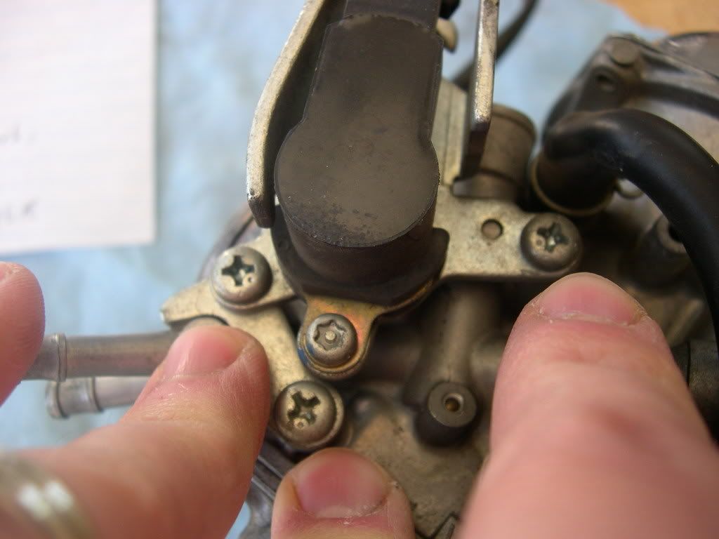
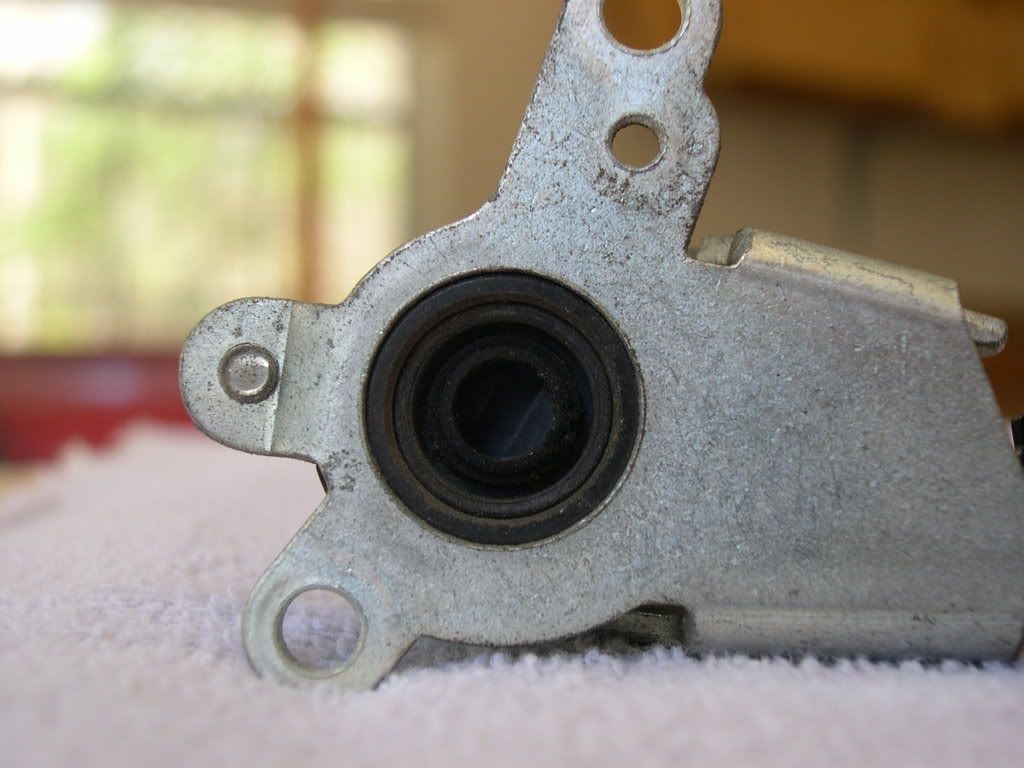
Step 13: Remove the three screws attaching the throttle position sensor and carburetor heater.
** Don't jack with the Torx screw.
![Image]()
Step 14: Remove the throttle position sensor with its bracket.
![Image]()
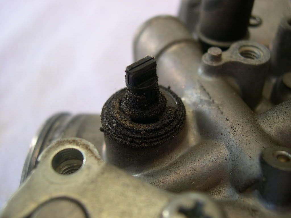
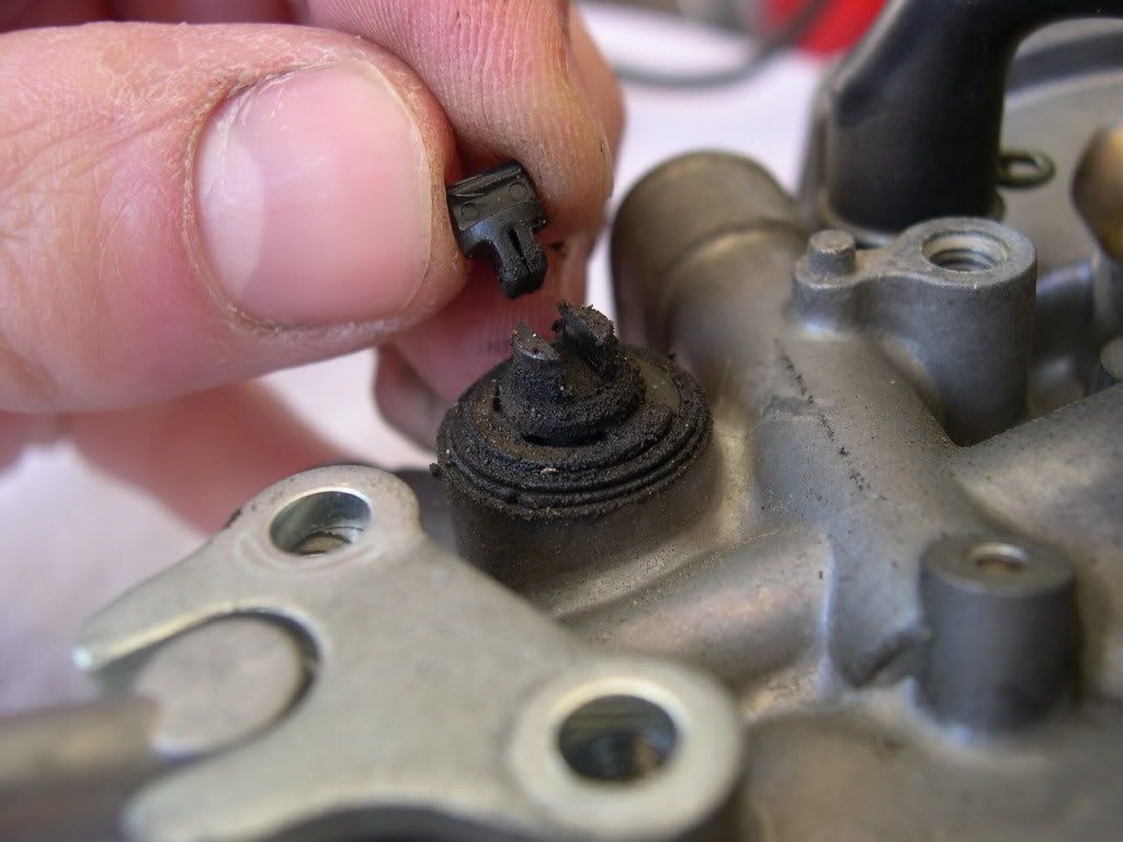
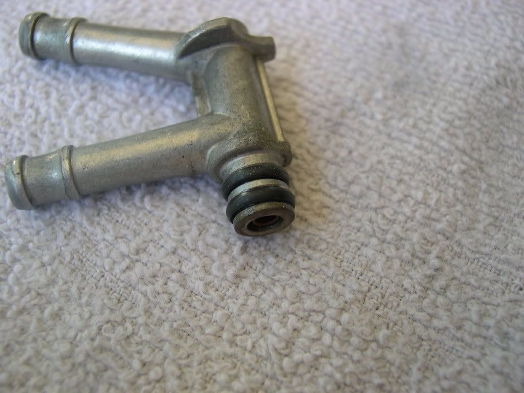
Step 15: Remove the connector joint from the throttle.
![Image]()
![Image]()
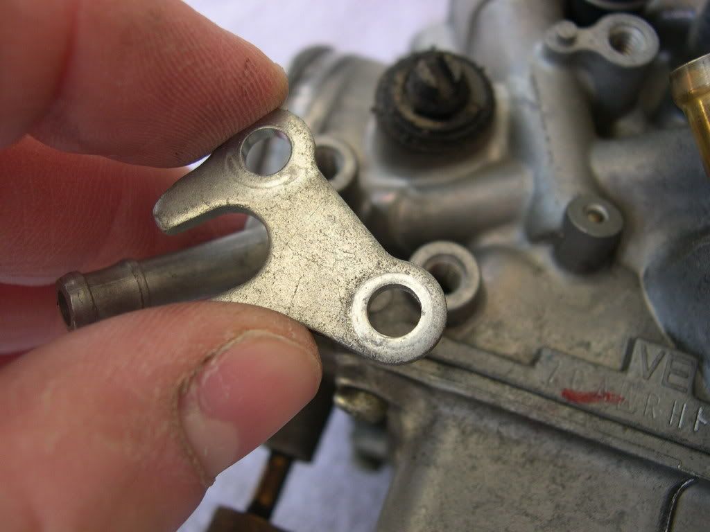
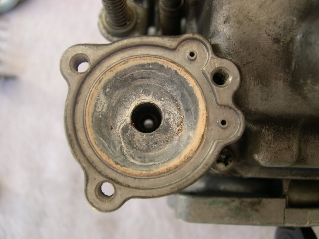
Step 16: Remove the carburetor heater setting plate.
![Image]()
Step 17: Remove the carburetor heater from the carburetor body.
![Image]()
![Image]()
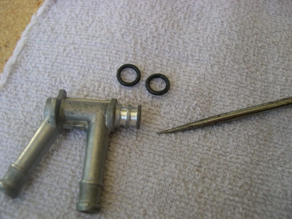
Step 18: Remove the O-rings from the carburetor heater.
** I used a small Craftsman pick to gently pry them up and off.
![Image]()
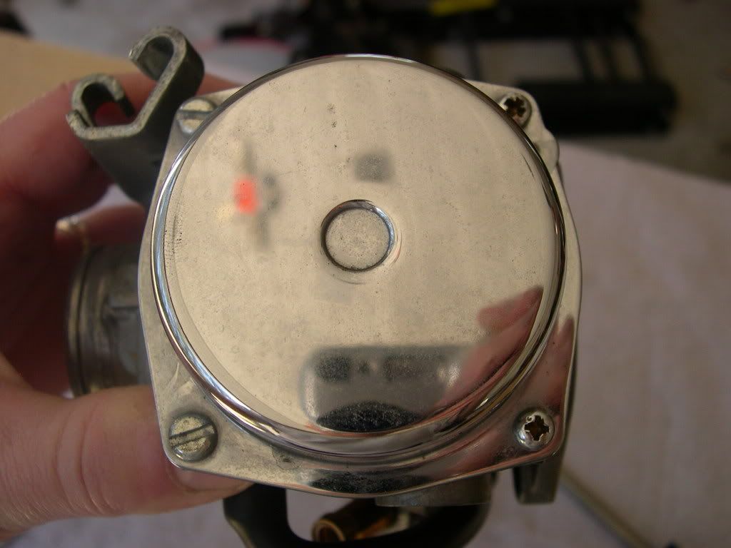
Step 19: Remove the four screws while holding the vacuum chamber cover.
![Image]()
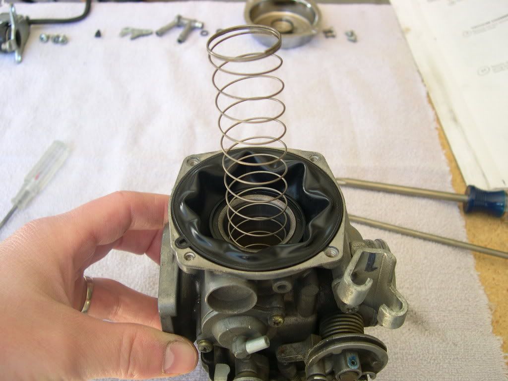
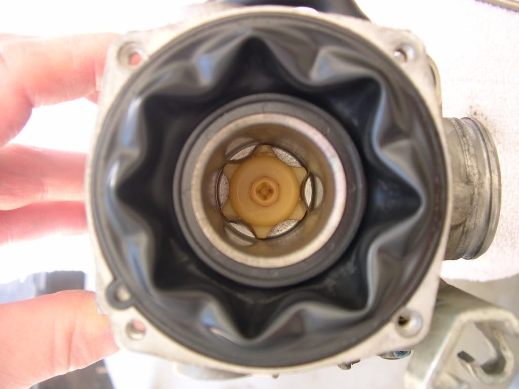
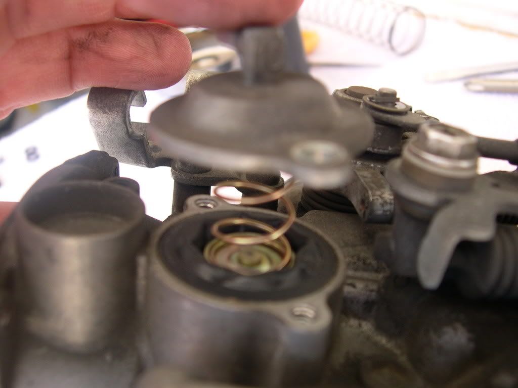
Step 20: Remove the vacuum chamber cover, compression spring and diaphragm/vacuum piston from the carburetor body.
![Image]()
Step 21: Turn the needle holder counterclockwise by using a screwdriver while pressing it in and release the holder flange from the vacuum piston. Remove the needle holder, spring & jet needle.
** I use an 8mm long socket with an extension on the yellow needle holder...mainly because I stripped the Phillips screw a long time ago when I was a noob. Also, I have a DynoJet Stage 3 jet kit, so my parts will look slightly different than the stock setup.
![Image]()
![Image]()
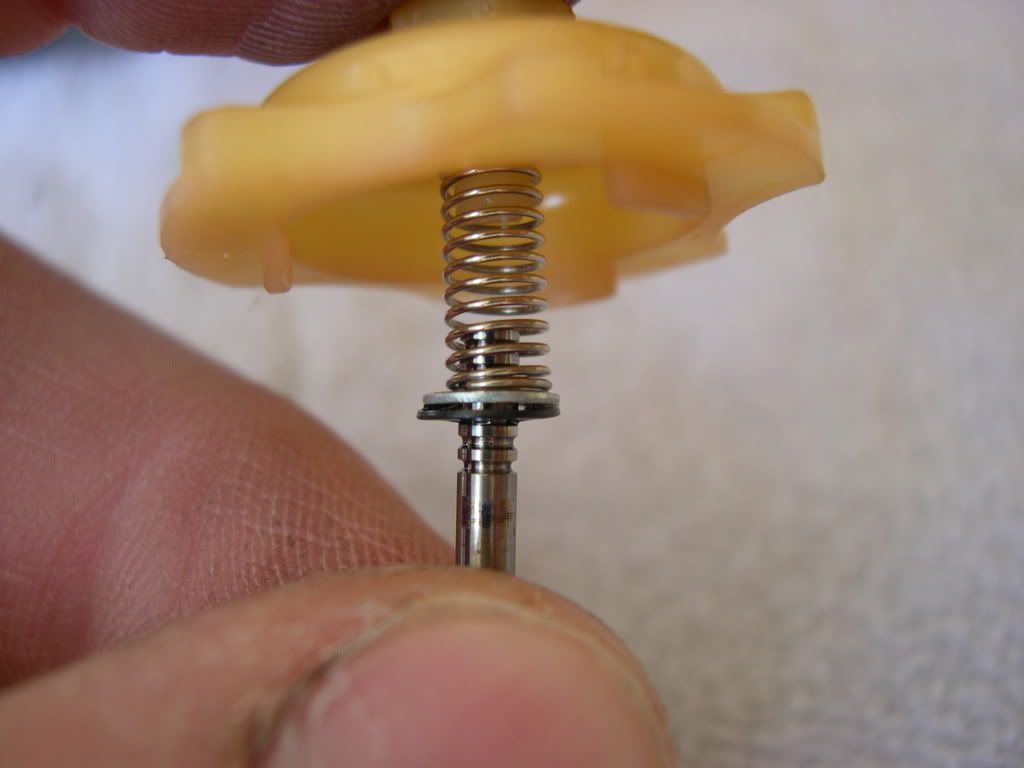
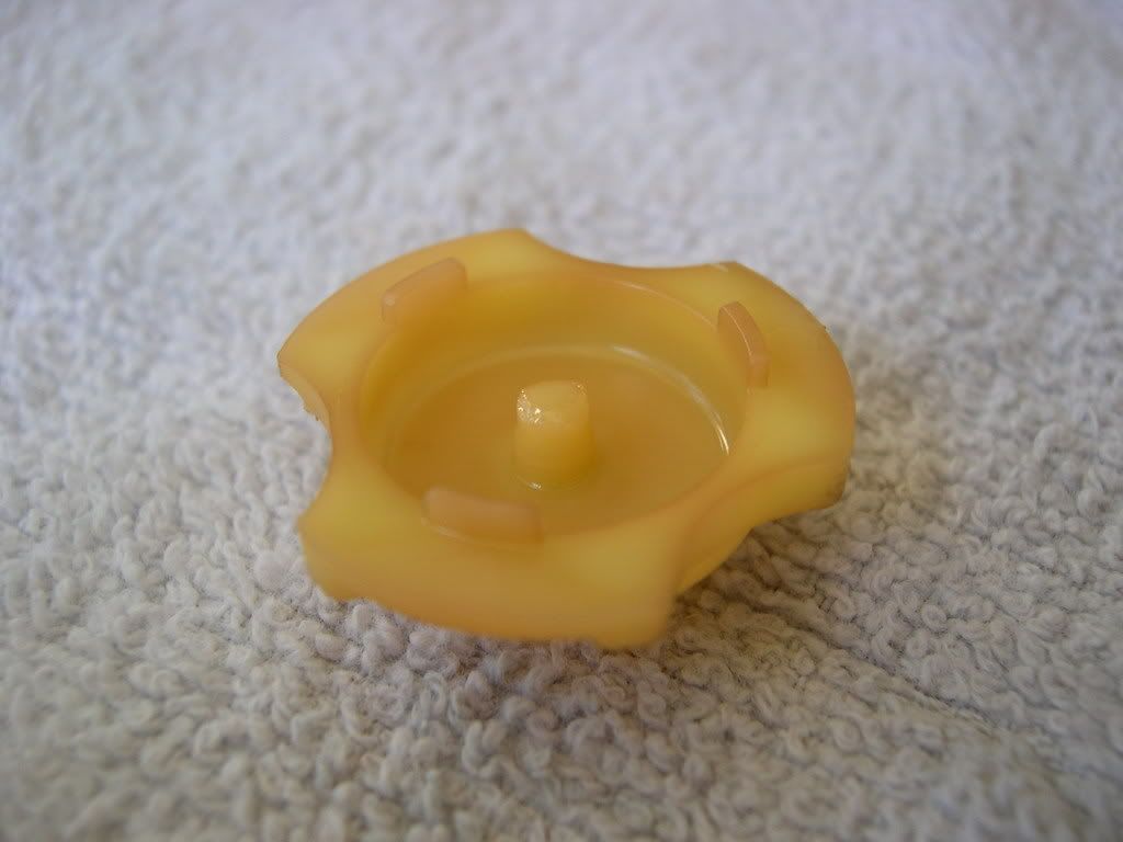
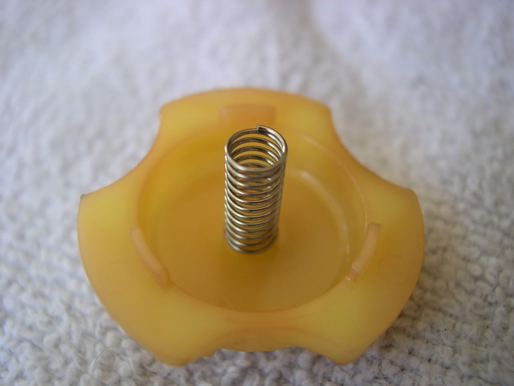
This is the infamous "tit" that gets clipped when doing a rejet, if you have to shim your stock needle or use a different needle from a kit.
![Image]()
The small spring screws onto the "tit". Be careful when taking it off/putting it back on that you don't stretch it out of shape.
![Image]()
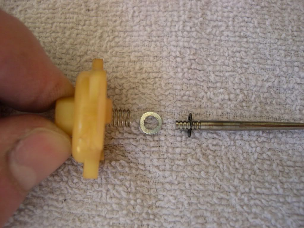
Here's the order of putting the DJ stuff back together. The e-clip is in the 4th groove from the top of the needle, then the washer sits on top of the e-clip, then the head of the needle goes into the spring.
![Image]()
For the stock parts, the stock needle (shimmed with washers underneath the head - Scar Mod) goes into the diaphragm/vacuum piston, then the spring sits on top of the stock needle's head.
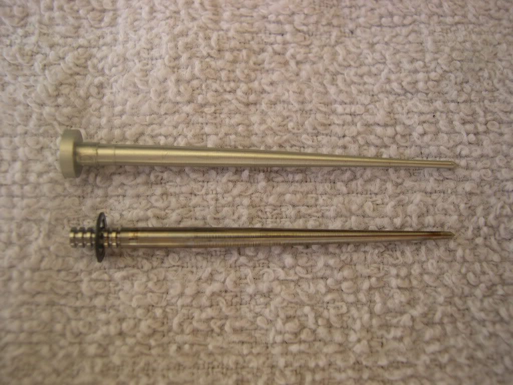
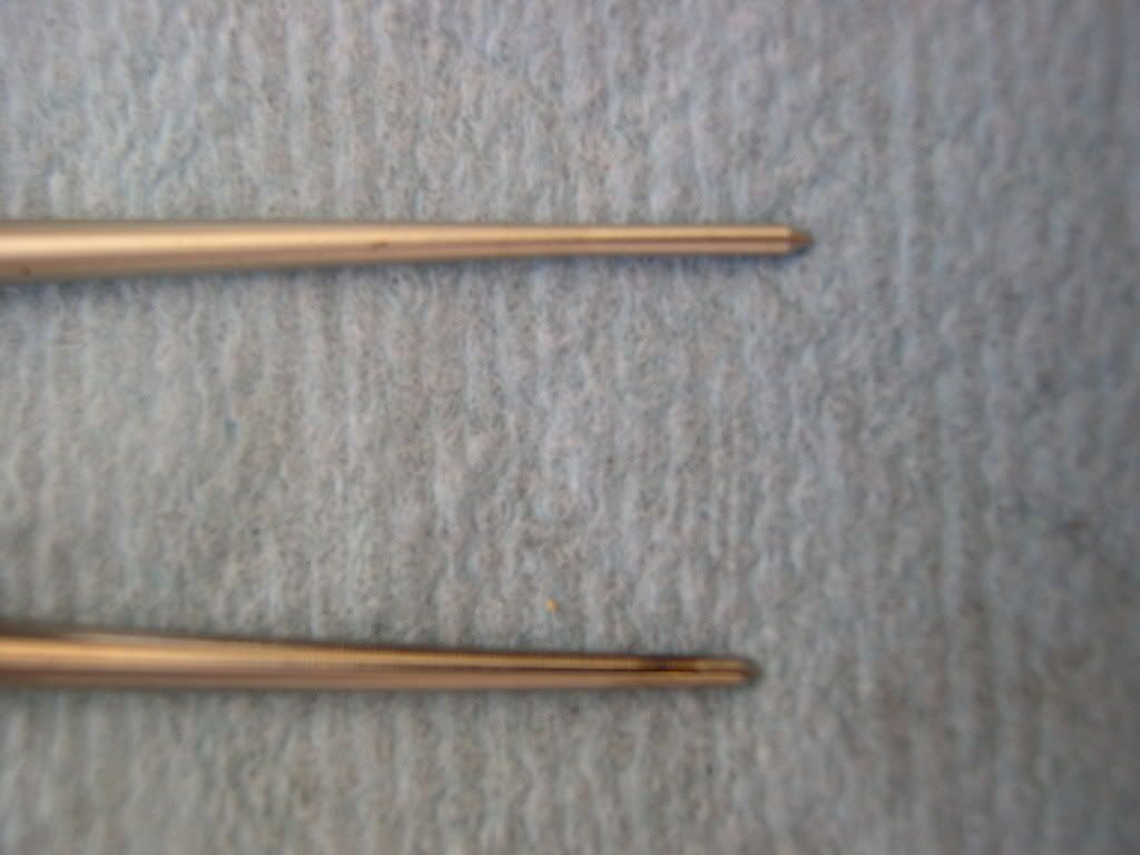
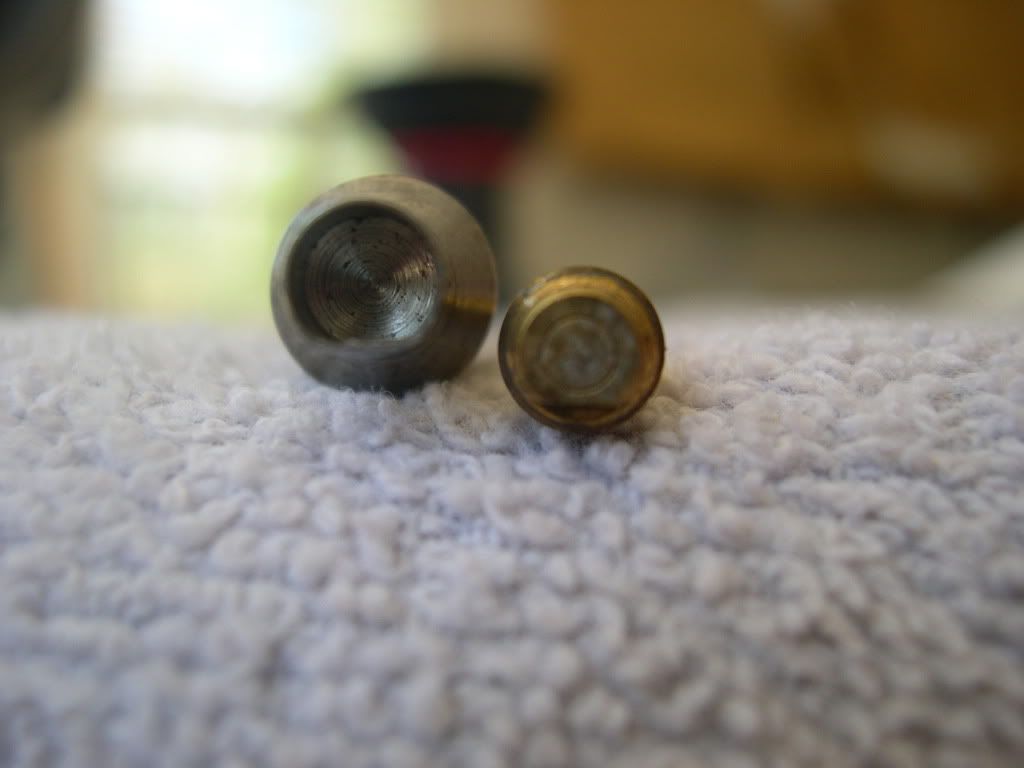
Here's a picture of a stock needle (top) and a DynoJet needle (bottom). Since the stock needle has no grooves, the Scar Mod washers must go underneath the head of the needle. This achieves the same results as moving the e-clip on the DynoJet needle. Also, notice that the two needles differ in their tapering.
![Image]()
![Image]()
Step 22: Check the jet needle for stepped wear. Check the vacuum piston for wear or damage. Check the diaphragm for pin holes, deterioration or other damage. Check the vacuum piston for smooth operation up and down in the carburetor body. Air will leak out of the vacuum chamber if the diaphragm is damaged in any way, even with just a pin hole.
![Image]()
![Image]()
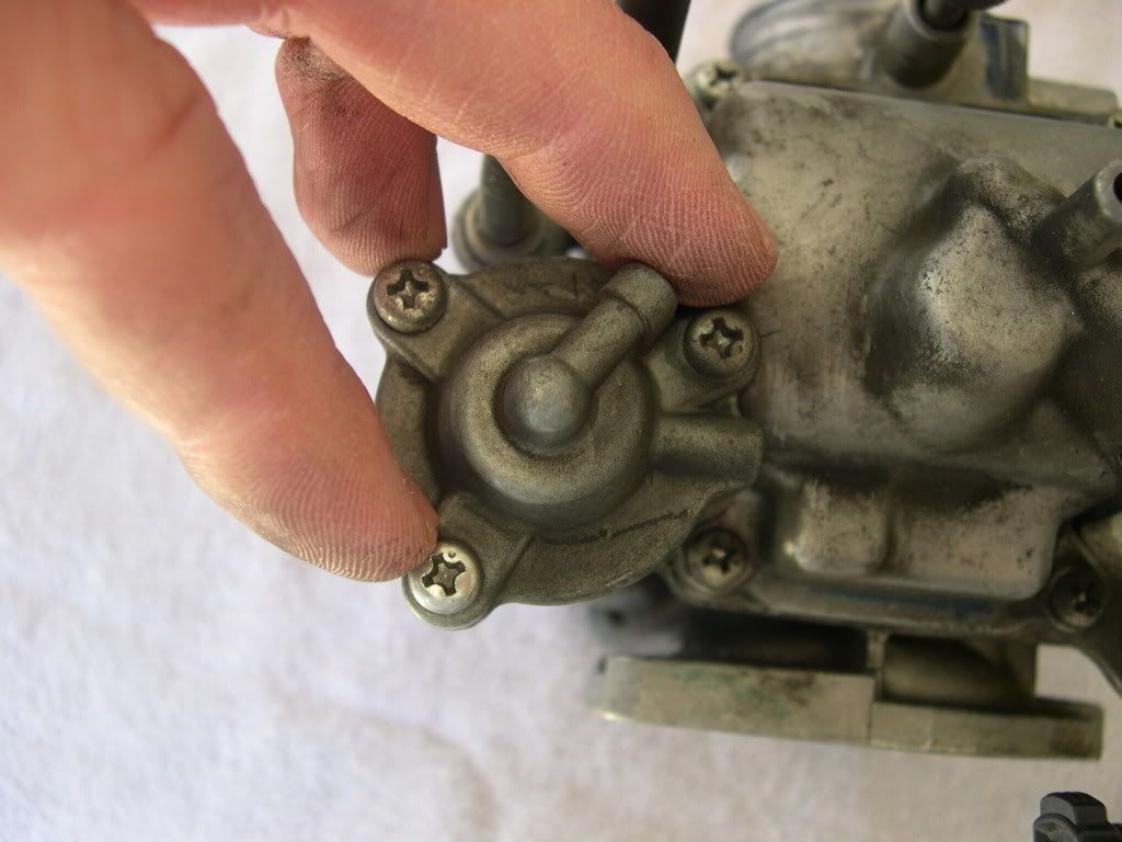
Step 23: Remove the two screws and washers while holding the air cut-off valve cover.
![Image]()
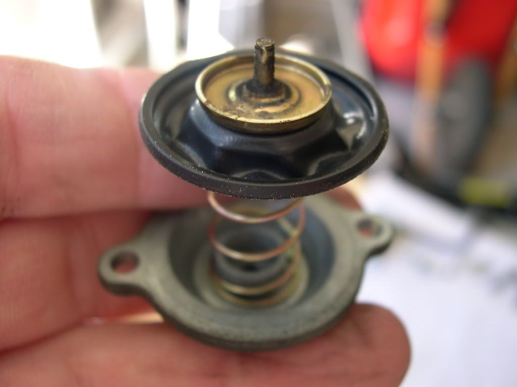
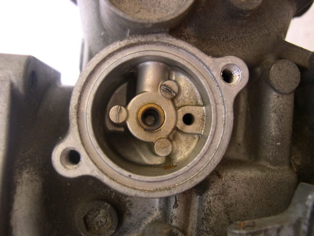
Step 24: Remove the air cut-off valve cover, spring and diaphragm from the carburetor body. Check the diaphragm for pin holes, deterioration or other damage. Check the diaphragm rod for wear or damage at the tip. Check the orifice in the valve cover and carburetor body for clogs or restrictions.
![Image]()
![Image]()
![Image]()
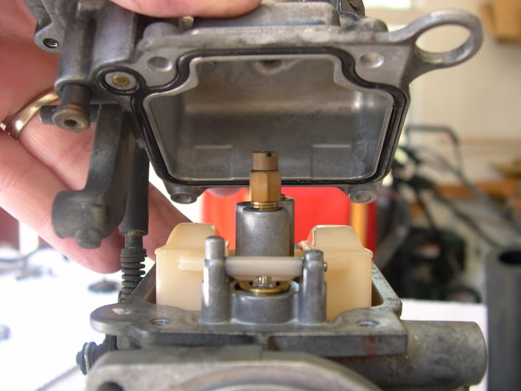
Step 25: Remove the three screws and washers while holding the accelerator pump cover.
![Image]()
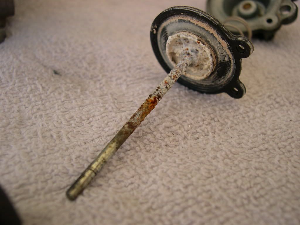
Step 26: Remove the accelerator pump cover, spring and diaphragm/rod from the float chamber. Check the diaphragm for pin holes, deterioration or other damage.
** As you can see, my rod is severely corroded. :shock: I used some 1500-grit sandpaper to clean it up, but I may just go ahead and order a replacement for good measure. Guess I wore out my accelerator pump, probably because my bike is orange! :mrgreen:
![Image]()
![Image]()
![Image]()
Step 27: Check the pump rod boot for deterioration or damage (small rubber boot in above picture - looks like an accordian).
** Gently pull the pump rod boot apart in good lighting to check for holes or tears.
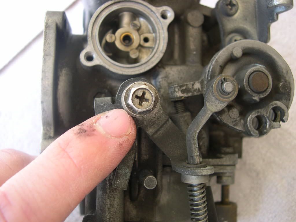
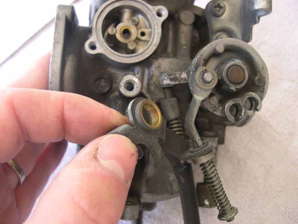
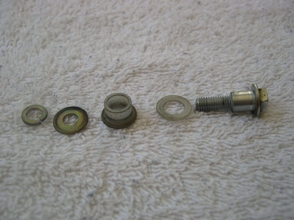
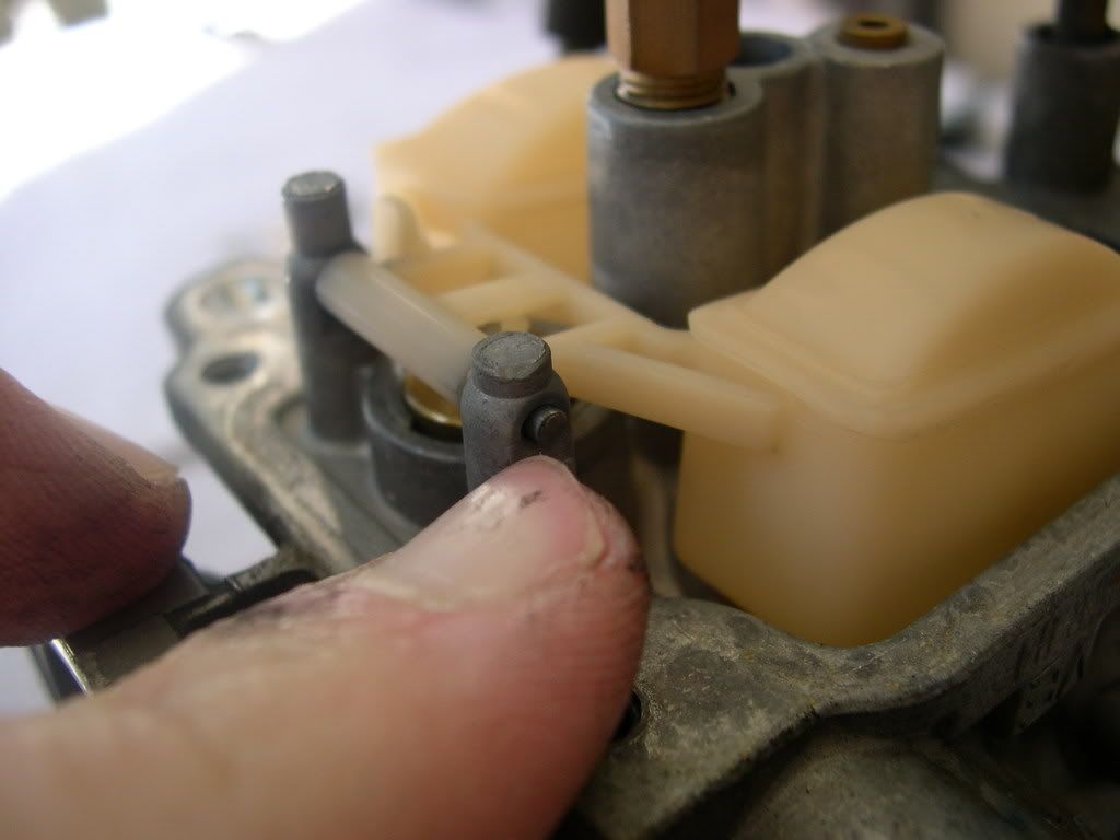
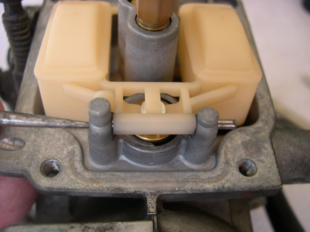
Step 28: Remove the bolt, plastic washer, accelerator pump link, collar, plain washer and spring (lock) washer from the float chamber.
** I used an 8mm socket on that bolt - much easier to break loose.
![Image]()
![Image]()
![Image]()
Step 29: Remove the four screws and the float chamber.
![Image]()
![Image]()
![Image]()
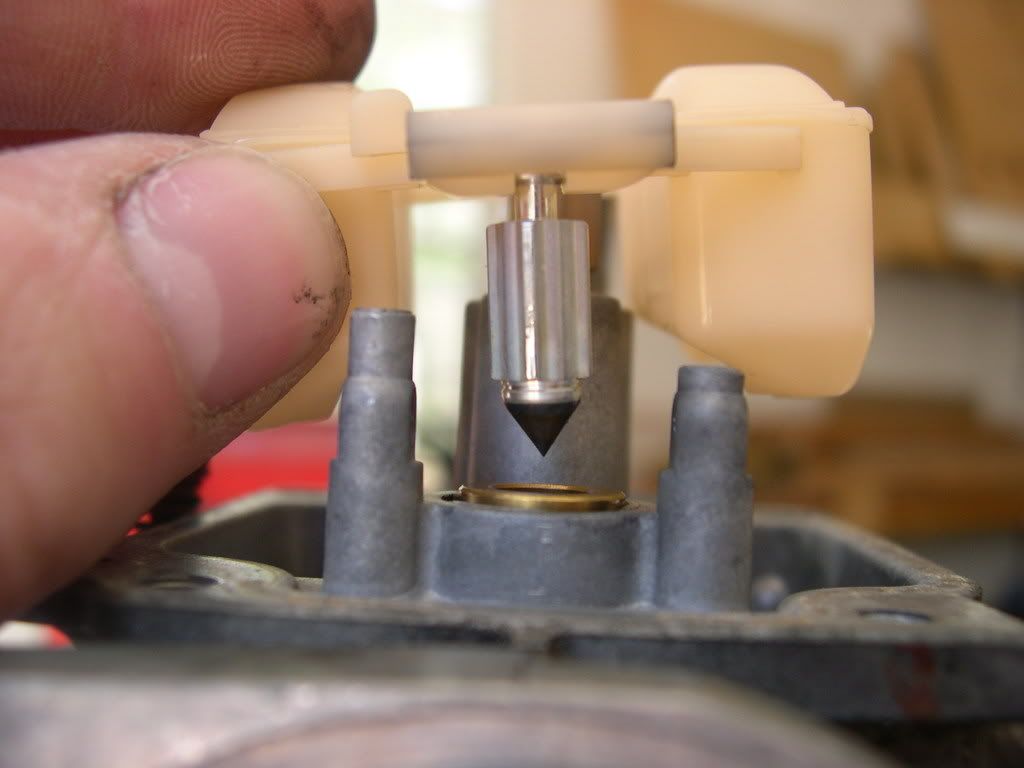
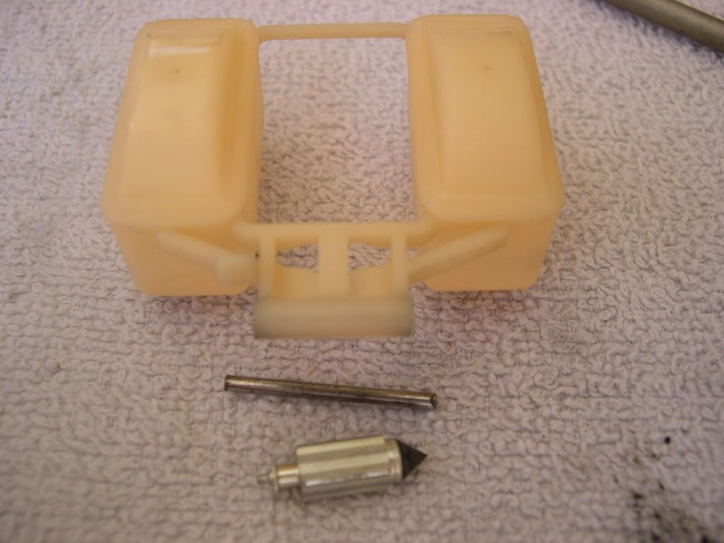
Step 30: Remove the float pin, float and float valve. Check the float for damage or fuel in the float.
** I used that same Craftsman pick to push the pin on one end so I could get it out on the other end.
![Image]()
![Image]()
![Image]()
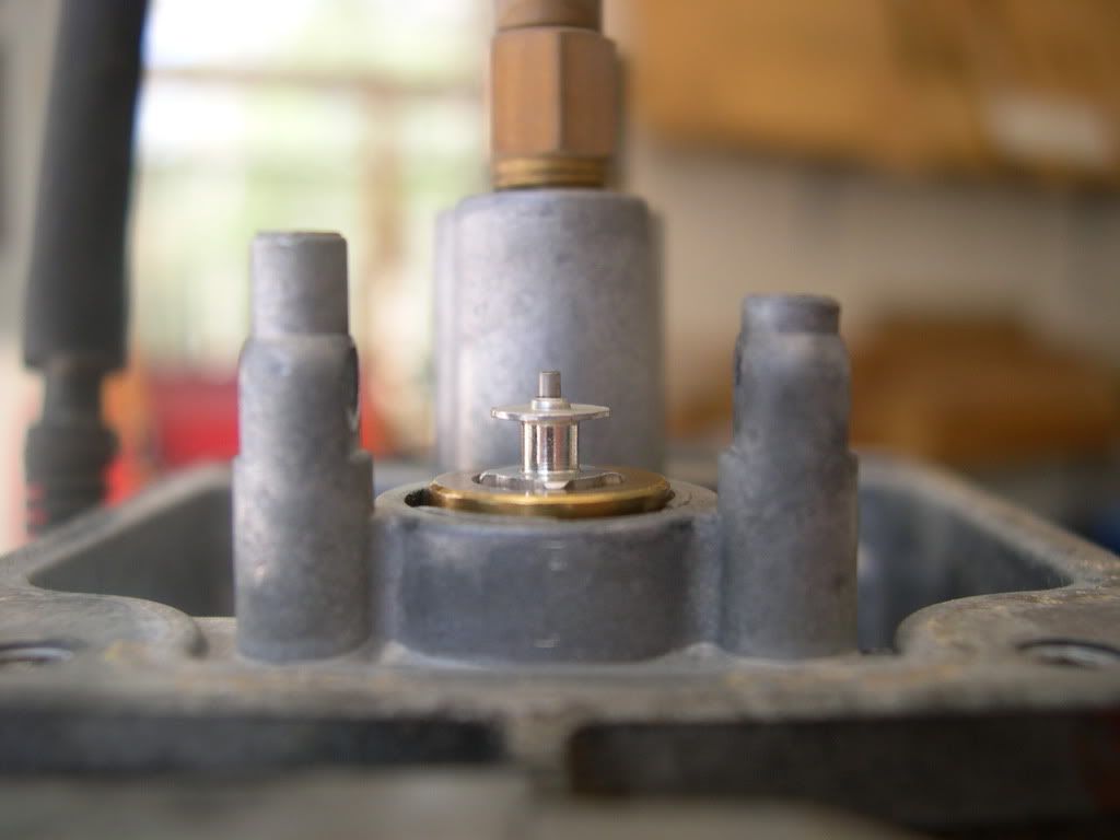
Step 31: Check the float valve and valve seat for scoring, scratches, clogs or damage. Check the tip of the float valve, where it contacts the valve seat, for stepped wear or contamination. Check the operation of the float valve.
![Image]()
![Image]()
![Image]()
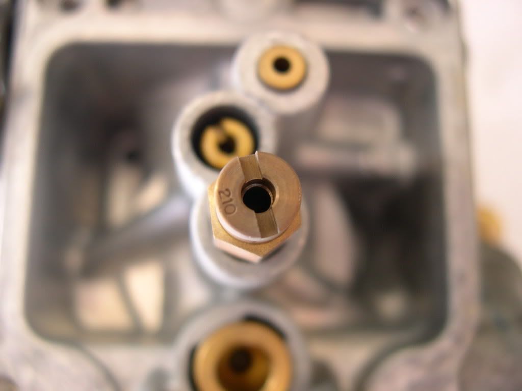
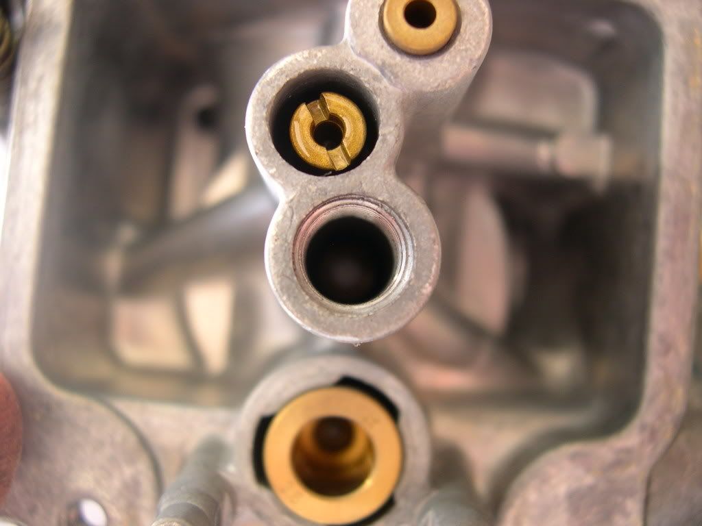
Step 32: Remove the following:
- Main Jet (mine is a 210 - used flat screwdriver)
- Needle Jet holder (used 7mm long socket)
- Needle Jet (used Craftsman pick to push it out)
- Slow Jet (also called pilot jet - used flat screwdriver)
Check each jet for wear and damage. Clean the jets with cleaning solvent and blow open with compressed air.
![Image]()
Main jet screwed into needle jet holder
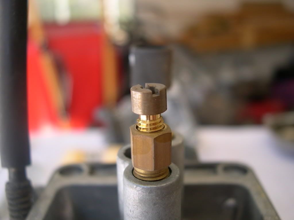
![Image]()
Needle jet holder by itself
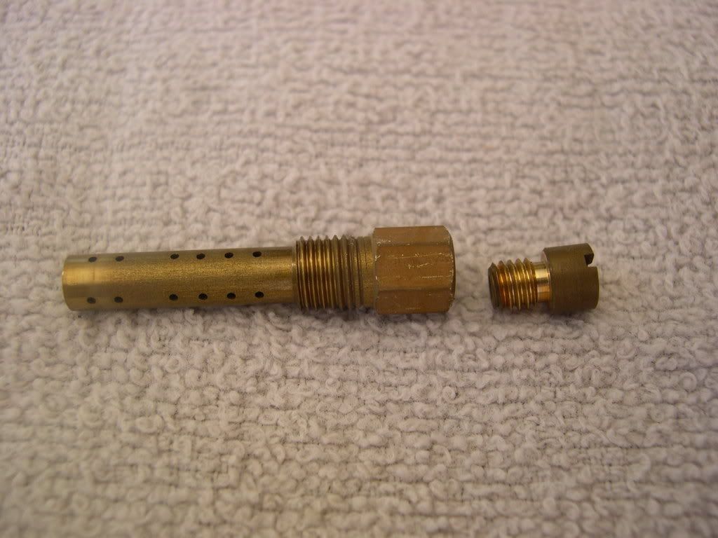
![Image]()
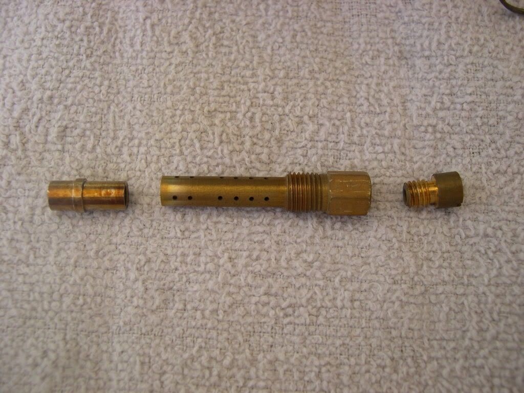
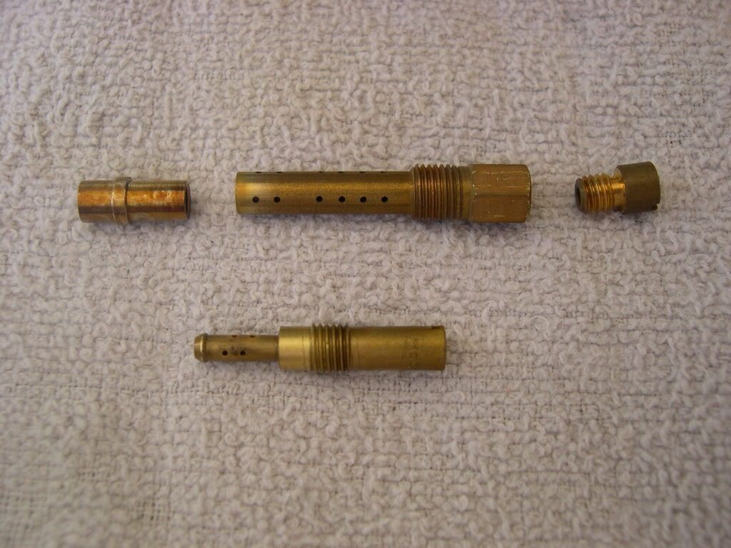
Needle jet holder (left) and main jet (right)
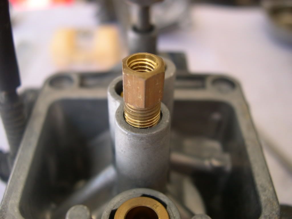
![Image]()
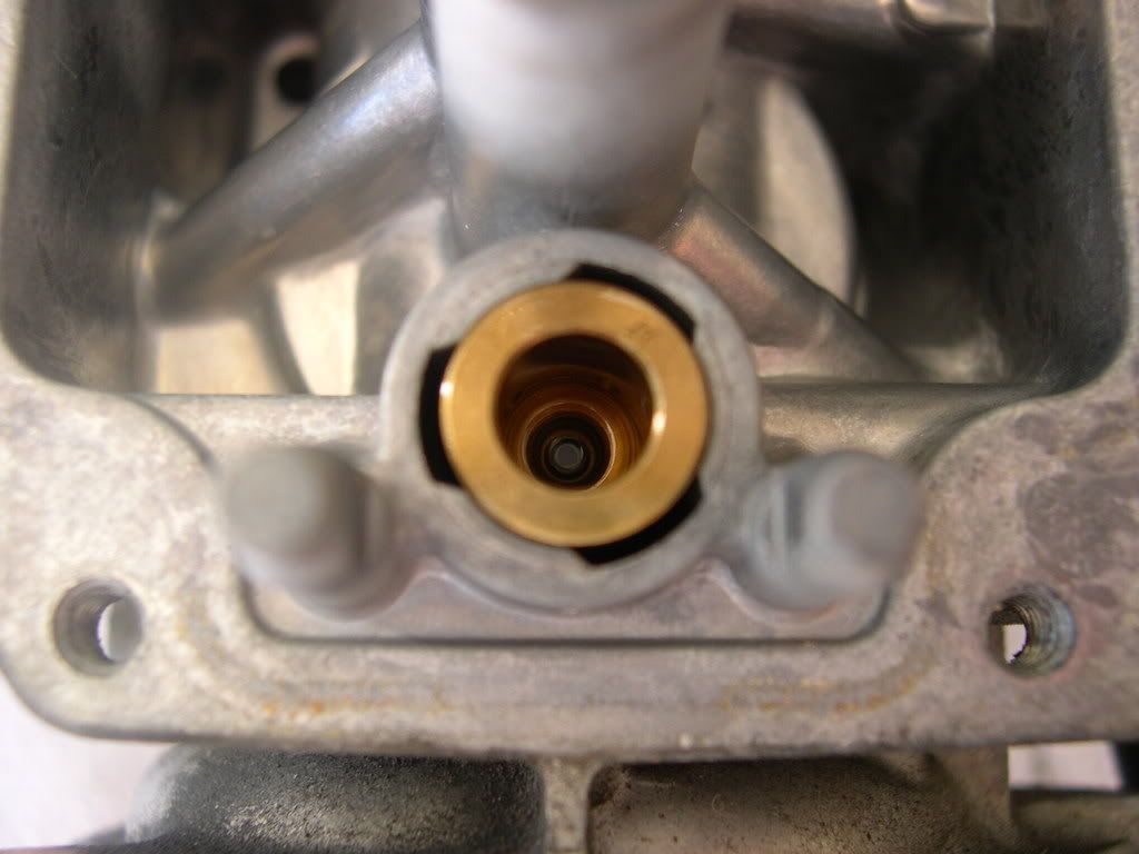
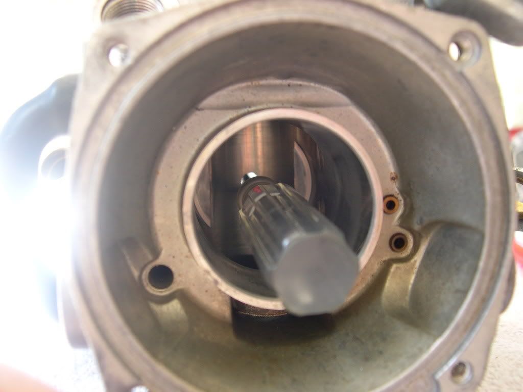
The vacated hole where the needle jet holder was screwed in has the needle jet down in there. I carefully used the Craftsman pick and gently pushed the needle jet from inside the carb and it came out of that threaded hole. It has to come out that way.
![Image]()
![Image]()
![Image]()
Needle jet (left), needle jet holder (middle) and main jet (right)
![Image]()
Slow jet (stock #55)
![Image]()
![Image]()
Slow jet (bottom) added to the previous group
![Image]()
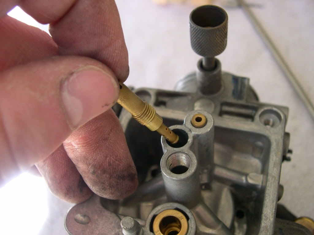
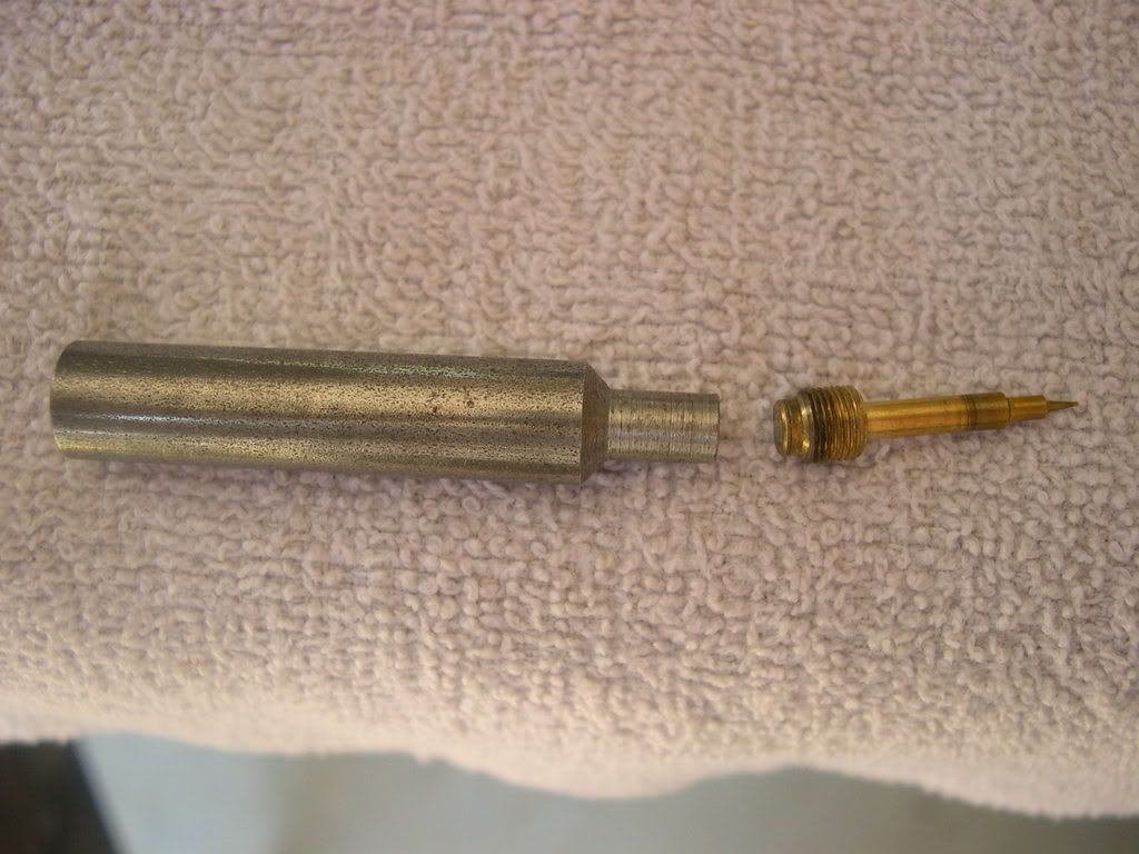
Step 33: Turn the pilot screw (also referred to as air/fuel screw) in and carefully count the number of turns until it seats lightly. Make a note of this to use as a reference when reinstalling the pilot screw.
** I have the SCain air/fuel screw made by SCain a long time ago. I will also show pictures of the stock screw and the "D" tool used to screw it in/out. What I did was use white-out to make a mark on the a/f screw, so I had a reference point when counting the number of turns. If you have the stock a/f screw, you can make a mark on the "D" tool that will accomplish the same thing.
![Image]()
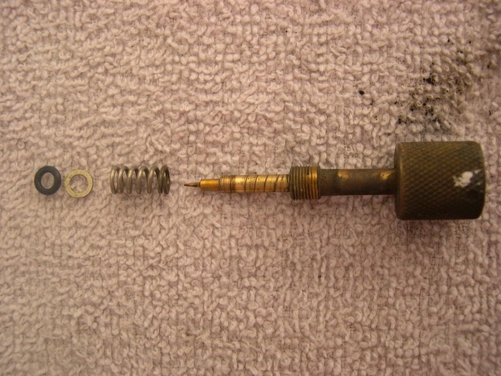
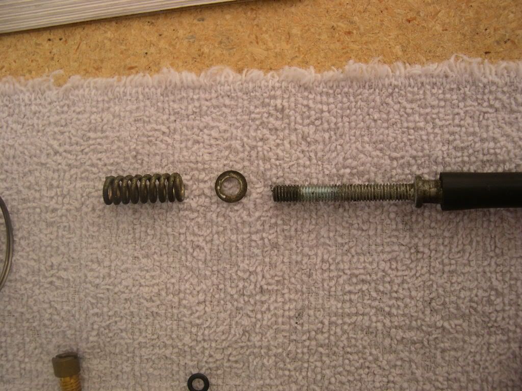
Step 34: Remove the pilot screw, spring, washer and )-ring. Check the pilot screw for wear and damage
![Image]()
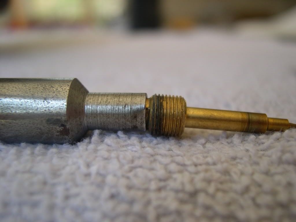
Here is the stock air/fuel screw, along with the "D" tool used to turn it. In the first picture, the flat side of the "D" shape is on the bottom of both the a/f screw and tool. The spring, washer and o-ring go on any available a/f screws in the same order.
![Image]()
![Image]()
![Image]()
I also removed the following:
Idle adjustment knob (simply unscrews)
![Image]()
![Image]()
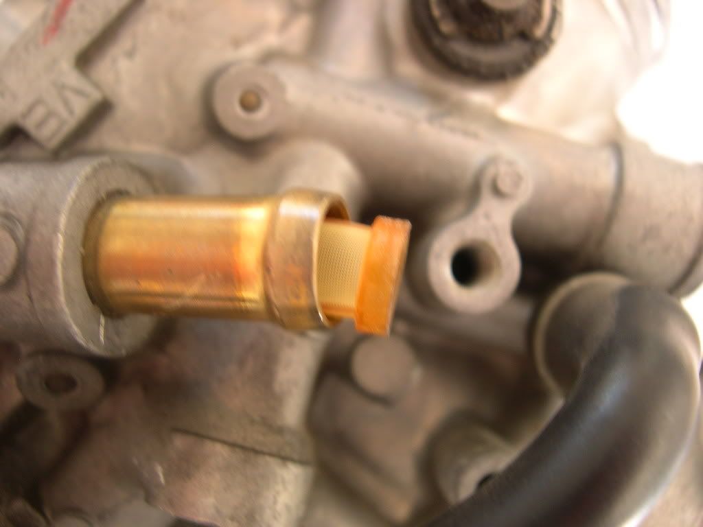
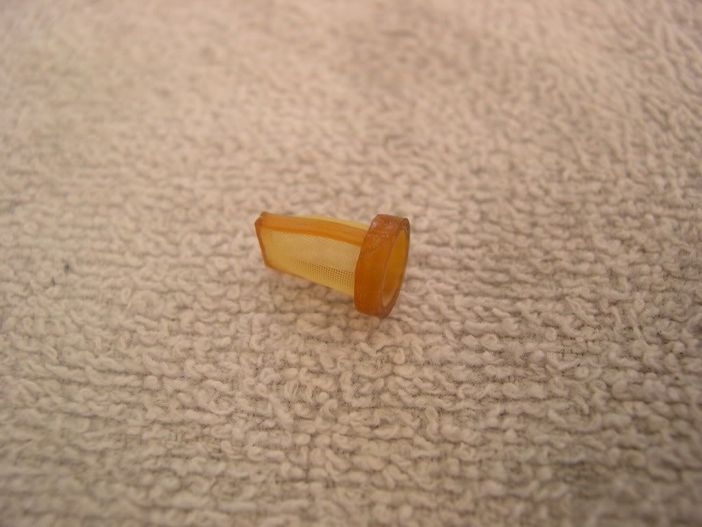
Small filter from fuel inlet
![Image]()
![Image]()
Carb vent tube that hangs off the left side of the carb (when viewed on the bike)
![Image]()
Cotter pin, washer and accelerator pump link
![Image]()
![Image]()
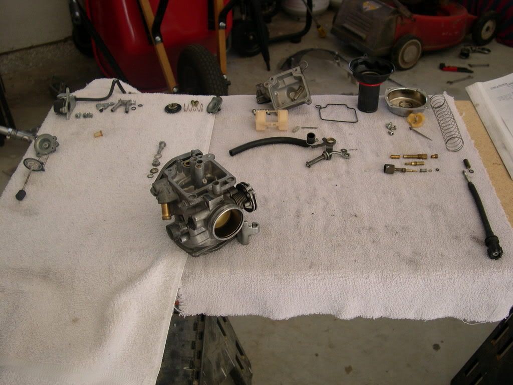
And here she is naked...and ready for a bath!!
![Image]()
![Image]()
![Image]()
![Image]()
Hope I can get all this back together! :yikes:
![Image]()
End of class!! :mrgreen::mrgreen:
Step 1: Drain the coolant.
** This involves taking the tank off, which I already had off anyway.
** You do not necessarily need to drain the coolant, but you will have to burp the air out of the system when everything is reconnected.
Step 2: Remove the right front cylinder head shroud (top fins).
Step 3: Remove the air cleaner housing (or aftermarket air kit).
Step 4: Disconnect the fuel hose from the carburetor.
Step 5: Slide the rubber cap off the starting enrichment (SE) valve nut.
Step 6: Loosen the SE valve nut and remove the SE valve from the carburetor.
** It helped to take the choke knob off it's holder on the pet****-side, which I did.
Step 7: Disconnect the throttle position sensor connector.
** It's the white connector that is next to the neck of the frame...you can't miss it. It's already unplugged in the following picture.
Step 8: Remove the throttle cables from the cable stay and disconnect them from the throttle drum.
** I'll get a picture of this when I put the carb back together...forgot to snap one during the tear-down.
Step 9: Disconnect the vacuum hose from the carburetor.

Step 10: Loosen the carburetor insulator band screw and remove the carburetor from the insulator.
Step 11: Disconnect the water hoses from the carburetor and remove the carburetor.
Step 12: Seal the intake manifold port with tape or a clean cloth to keep dirt and debris from entering the engine.
Step 13: Remove the three screws attaching the throttle position sensor and carburetor heater.
** Don't jack with the Torx screw.
Step 14: Remove the throttle position sensor with its bracket.
Step 15: Remove the connector joint from the throttle.
Step 16: Remove the carburetor heater setting plate.
Step 17: Remove the carburetor heater from the carburetor body.
Step 18: Remove the O-rings from the carburetor heater.
** I used a small Craftsman pick to gently pry them up and off.
Step 19: Remove the four screws while holding the vacuum chamber cover.
Step 20: Remove the vacuum chamber cover, compression spring and diaphragm/vacuum piston from the carburetor body.
Step 21: Turn the needle holder counterclockwise by using a screwdriver while pressing it in and release the holder flange from the vacuum piston. Remove the needle holder, spring & jet needle.
** I use an 8mm long socket with an extension on the yellow needle holder...mainly because I stripped the Phillips screw a long time ago when I was a noob. Also, I have a DynoJet Stage 3 jet kit, so my parts will look slightly different than the stock setup.
This is the infamous "tit" that gets clipped when doing a rejet, if you have to shim your stock needle or use a different needle from a kit.
The small spring screws onto the "tit". Be careful when taking it off/putting it back on that you don't stretch it out of shape.
Here's the order of putting the DJ stuff back together. The e-clip is in the 4th groove from the top of the needle, then the washer sits on top of the e-clip, then the head of the needle goes into the spring.
For the stock parts, the stock needle (shimmed with washers underneath the head - Scar Mod) goes into the diaphragm/vacuum piston, then the spring sits on top of the stock needle's head.
Here's a picture of a stock needle (top) and a DynoJet needle (bottom). Since the stock needle has no grooves, the Scar Mod washers must go underneath the head of the needle. This achieves the same results as moving the e-clip on the DynoJet needle. Also, notice that the two needles differ in their tapering.
Step 22: Check the jet needle for stepped wear. Check the vacuum piston for wear or damage. Check the diaphragm for pin holes, deterioration or other damage. Check the vacuum piston for smooth operation up and down in the carburetor body. Air will leak out of the vacuum chamber if the diaphragm is damaged in any way, even with just a pin hole.
Step 23: Remove the two screws and washers while holding the air cut-off valve cover.
Step 24: Remove the air cut-off valve cover, spring and diaphragm from the carburetor body. Check the diaphragm for pin holes, deterioration or other damage. Check the diaphragm rod for wear or damage at the tip. Check the orifice in the valve cover and carburetor body for clogs or restrictions.
Step 25: Remove the three screws and washers while holding the accelerator pump cover.
Step 26: Remove the accelerator pump cover, spring and diaphragm/rod from the float chamber. Check the diaphragm for pin holes, deterioration or other damage.
** As you can see, my rod is severely corroded. :shock: I used some 1500-grit sandpaper to clean it up, but I may just go ahead and order a replacement for good measure. Guess I wore out my accelerator pump, probably because my bike is orange! :mrgreen:

Step 27: Check the pump rod boot for deterioration or damage (small rubber boot in above picture - looks like an accordian).
** Gently pull the pump rod boot apart in good lighting to check for holes or tears.
Step 28: Remove the bolt, plastic washer, accelerator pump link, collar, plain washer and spring (lock) washer from the float chamber.
** I used an 8mm socket on that bolt - much easier to break loose.
Step 29: Remove the four screws and the float chamber.

Step 30: Remove the float pin, float and float valve. Check the float for damage or fuel in the float.
** I used that same Craftsman pick to push the pin on one end so I could get it out on the other end.
Step 31: Check the float valve and valve seat for scoring, scratches, clogs or damage. Check the tip of the float valve, where it contacts the valve seat, for stepped wear or contamination. Check the operation of the float valve.
Step 32: Remove the following:
- Main Jet (mine is a 210 - used flat screwdriver)
- Needle Jet holder (used 7mm long socket)
- Needle Jet (used Craftsman pick to push it out)
- Slow Jet (also called pilot jet - used flat screwdriver)
Check each jet for wear and damage. Clean the jets with cleaning solvent and blow open with compressed air.
Main jet screwed into needle jet holder
Needle jet holder by itself
Needle jet holder (left) and main jet (right)
The vacated hole where the needle jet holder was screwed in has the needle jet down in there. I carefully used the Craftsman pick and gently pushed the needle jet from inside the carb and it came out of that threaded hole. It has to come out that way.

Needle jet (left), needle jet holder (middle) and main jet (right)
Slow jet (stock #55)

Slow jet (bottom) added to the previous group
Step 33: Turn the pilot screw (also referred to as air/fuel screw) in and carefully count the number of turns until it seats lightly. Make a note of this to use as a reference when reinstalling the pilot screw.
** I have the SCain air/fuel screw made by SCain a long time ago. I will also show pictures of the stock screw and the "D" tool used to screw it in/out. What I did was use white-out to make a mark on the a/f screw, so I had a reference point when counting the number of turns. If you have the stock a/f screw, you can make a mark on the "D" tool that will accomplish the same thing.
Step 34: Remove the pilot screw, spring, washer and )-ring. Check the pilot screw for wear and damage
Here is the stock air/fuel screw, along with the "D" tool used to turn it. In the first picture, the flat side of the "D" shape is on the bottom of both the a/f screw and tool. The spring, washer and o-ring go on any available a/f screws in the same order.
I also removed the following:
Idle adjustment knob (simply unscrews)

Small filter from fuel inlet
Carb vent tube that hangs off the left side of the carb (when viewed on the bike)
Cotter pin, washer and accelerator pump link


And here she is naked...and ready for a bath!!
Hope I can get all this back together! :yikes:
End of class!! :mrgreen::mrgreen:


